Browsing posts in: Electronics

WS2811 expander part 3: PCB Revisions again…

More revisions.

I posted the design to /r/PrintedCircuitBoard, and of the comments said:

“Do you need pullups on the outputs of WS2811?”

And of course, I was confident the answer was “no”. For about 5 seconds. And then I measured the WS2811 I have in my breadboard; it gave a nice solid sink when it was on, and when it was off, just a fraction of a volt. Clearly not up to sourcing current to the NPN transistor.

The most likely explanation is that it’s an open collector output:

The collector on the output transistor is just left hanging – it’s only collected to the external pin. The voltage on an open collector can float up above the internal voltage of the IC as long as you don’t exceed the maximum voltage of the transistor

Open collectors are really useful if you want to have a bus architecture with multiple components able to pull the bus low, or if you aren’t sure what voltage of the output is going to be. Since the WS2811 can be used to drive LEDs tied to either 5V or 12V, it makes perfect sense. And it is confirmed by the internets.

Which means that the circuit needs to get a tiny bit more complicated:

image

Another pullup resistor is added to the mix. Really not a problem from the cost and assembly perspective as the design goes from 9 resistors to 12 resistors.

But, can I fit it in the current board layout without making it bigger?

I should probably add a parenthetical note here that says it’s often easier to go with a bigger layout, and in fact if you are going to hand solder a board, you *should* go with a bigger layout. Though I’m not sure how practical it is to solder the MOSFETS by hand since the base pad is so big…

Anyway, here’s what the board looked like before:

I need to put a resistor between each of the traces that head from the WS2811 over to the transistors. Hmm.

I initially just tried to fit them in there, and with a big of rerouting, I was able to make it fit. Technically.

Then I decided that it would be a lot easier if I moved the vertical ground trace underneath the transistors and used that to provide the ground connection to the transistors. That meant I could move the VCC vias around more easily, and could do the following:

image

The fit in reasonably well.

I *think* it’s ready to order the first version of the board, but there’s one more step. I now have on hand the WS2811 ICs and both kinds of transistors. So, I printed out a design with the copper layers shown, and did a test to see if the components really fit on the board.

image

That shows the WS2811 on the left, the MOSFET on the right, one of the NPN transistors and then a tiny 0805 10K resistor at the top. Everything looks like it will fit fine.

I ordered 3 boards for $7.10 from Oshpark, which is my usual supplier for prototype boards if they are small.


WS2811 expander

I’m starting a new decorations project that will involve a fair number of standard LEDs, but not addressable ones. I have a few different use scenarios:

  1. Plug into a standard USB power supply.
  2. Power directly with 120 VAC.
  3. Power either with 5V or 12V and have an easily way to control brightness…

The first two are just wiring, but the third needs something more. My target market is quite used to using WS2812 addressable LEDs, so I’m going to build something that works in that environment.

Quick requirements list:

  1. Runs on 5V or 12V.
  2. Uses WS2812 protocol.
  3. Can drive significant loads (at least 10 amps).
  4. Small and cheap

The second requirement is pretty simple; you can buy the WS2811, which works exactly the same way as the WS2812 lights but is in a separate package. And it very conveniently has a little internal power supply that can use 5V or 12V by changing the value of one resistor. Here’s a typical 5V circuit:

image

Looks very nice, and almost does what I want, except that it’s designed to only sink 18.5 mA, which is quite a bit less than my 10 amp goal. I don’t strictly have a use for 10 amps right now, but I will likely need at least 1 amp for some uses.

So, I’m going to lean on the IRLR7821PbF MOSFET that I used in my backyard controller, which it looks like I can get for about $0.14 each. It’s pretty easy to use:

image

I will just drive the gate of the MOSFET with the output of the WS2811, and when the MOSFET turns on, it will pull the LED1 line low, turning on the LED.

Except… the WS2811 outputs are active low, and the MOSFET in this arrangement is active high. So

image

We add an NPN transistor. If the input is low, the transistor is off and the gate on the MOSFET is pulled high by the 10K resistor. If the input is high, the transistor is on, the gate is pulled low, and the MOSFET is off.

That will be duplicated for all three channels, and we end up with the following:

image

R9 and R10 are really just empty holes; you bridge R9 with wire if you want to use 5V and R10 if you want to use 12V.

I unfortunately generally forget to take snapshots during PCB design, so here’s the V1 state:

image

The MOSFETs have lots of 4s on them – I don’t know why – and to the left are the bipolar transistors and the resistors required for that part of the circuit.

The power input holes and the LED holes are designed to use Molex KK 396 headers and connectors so you can either use those or hand wire.

The lower left shows the jumper locations to set voltage.

All resistors are 0603 sized; that makes them compact but still relatively easy to populate.

The only weirdness are the three through-holes next to the LED terminals. I need to tie that backside ground trace to the frontside MOSFET terminal, but I was having trouble fitting enough vias to carry the current. Instead, I just used the through holes, which will be filled with solder and therefore be able to carry plenty of current.

The board is about 40mm x 28mm in size. I might jump up to 0805 resistors to make it a little easier to fabricate.

Before I send it off to be fabricated, I need to have the transistors in hand so I can verify the layout works.


Backyard controller design #4 – Software

The controller software lives here on github. My current software development environment is Visual Studio Code with Platform IO installed on top of it. It’s quite a bit better than the Arduino IDE for my usage patterns.

I’ve done my best to build a flexible and well-abstracted design. With the exception of main.cpp, all of the C++ classes are written in the include (.h) files so that I don’t have to deal with multiple files per class.

Here are the classes and a brief description of what they do:

  • Action – takes in a textual description of an action (on, off, toggle, plus some dim levels) and converts it to a numeric value. This is a nicer pattern to use than an enum as the parsing code can live here.
  • Device – an abstraction for a device that I want to be able to control. It has a text name, a group name, an output pin, and a timeout (in 10 mS units). If you pass it a name and an action, if will implement that action if the name matches either the text name or the group name of the device.
  • HardWiredController – the physical controller (not yet built) has a group of switches connected via resistors to the input line, giving a varying voltage based on which switch is pressed. This code uses the ADC in the ESP to get the current value, figures out what button was pushed, and performs the appropriate command.
  • Main.cpp – the main setup and loop code. Mostly just delegates out to other classes.
  • MainPage.h – the text of the web interface page for the controller
  • Manager.h – the manager for all the devices. It creates an array of devices and then handles dispatching commands to them, getting status strings, handling timeouts, etc.
  • OnIfAnyDevice.h – the 12V power supply needs to be turned on if any of the lights are on. This class looks at the state of the devices passed in through the constructor and turns itself on if any of them are on.
  • StairSensing.h – The program needs to turn on the house lights if the stair lights are turned on. This code tracks whether the stair lights have been turned on and switches the house lights on and off as necessary.
  • WebServer.h – The code that handles requests for the UI page and url action commands.

The main loop runs with a 10mS delay so that every time through the loop is roughly that long; that is needed to implement the timeouts in the device class. I could have done this in a more sophisticated manner but what I did is clear and good enough for the requirement.

The Manager and Device classes warrant a bit more discussion. They are use a software pattern called “Chain of Responsibility”; there are basically 5 devices that all look alike, and the manager just passes the action through to all of them and the device that the action belongs to deals with it.

This vastly simplifies the manager class – otherwise it would have to check every string and figure out which device to pass it to – and makes it really easy to implement group devices; the “lights” group refers to all light devices. It also makes it easier to implement the OnIfAnyDevice class, which otherwise would have required special case code.


Backyard controller design #3–Board & construction

In our last installment, we were trying to decide whether to hand-wire the controller or to go with the PC board. The PC board won out handily since it only cost $13.30 for the standard 3 boards from OSHPark.

Here’s a picture of the board with populated with the 3 MOSFETs and 5 resistors. I did the solder paste application by hand since I only need to do one of these. Standard solder-paste since the MOSFETS may switch up to around 8 amps and therefore may get a bit warm.

image

And here’s a picture after the reflow. Reflow done in my Controleo 3 toaster oven reflow-er. Looks just fine.

image

One little comment: One problem I had during layout was how to connect the top pin of the MOSFETS to ground in a way that could flow enough current from the front to the back. My first design started with a number of vias, but I didn’t like it. Then I realize I had an easier solution; I just use a single through-hold pad and hand filled it with solder. It will carry far more current than I need.

Build

In my original concept all of this was going to fit inside of a double-gang electrical outlet box, but I realized that a) I’d rather mix as little low voltage and line voltage as possible and b) the box I used was only half-depth, so no room. Which argued to use a box and mount it to the house. Here’s the one I chose:

image

It’s a good size and has mounting bars. I don’t really need the gasket because I’ll be cutting holes for the wires. $11.60.

The next order of business was to figure out how to connect the big 12-gauge lighting wire to small connections on the board. I am lucky enough to have a good local Electronics store 15 minutes from my house (if you are in the Seattle area, Vetco is worth a trip), and that yielded a couple of terminal strips:

I think I bought two for $4.99 each, plus I bought some 18 gauge wire to go from the board to the strip (the big holes on the board can only support 18 gauge. Which led to this:

image

Those are all of the connections that take big wire, and the terminal strip color-coded with Sharpies.

Yes, I know I messed up the sequence; the 12V in at the lower right portion of the board really wanted to be there for each connection to the three 12V outputs. And it turns out that the wemos nodemcu layout I used was upside down, so the ESP-12 is hiding underneath the module rather than on top of it. There are female headers soldered to the board and male headers soldered to the nodemcu board. This allows me to easily remove it for reprogramming. Which was already required a time or two.

I used the same technique for the remaining controls I needed but they don’t map 1:1 to the board.

image

Here’s a few steps at once. I found an MDF cutoff and used that as the back of the board, and the screws that mount it also mount the terminal strips.

On the upper right terminal strip we have 120VAC coming into the box; that connects to a 5V power supply. There is a small 2AMP SSR that I had lying around that will switch on the 200  watt 12V power supply when it is needed. The “Pump on” output will connect to a similar SSR in the remote electrical box.

I did a full test of all the features, and they all worked. Well, except for the switching for the 12V power supply, which was broken by a refactoring I did in the software.

Umbrella lights

We have a shade umbrella with some chair under it, and one of the requirements was to have some light underneath it. I didn’t find any premade ones that I liked, so I bought 5 meters of 12V led strip and made my own. I made 8 strips that were 16” in length, attached wire, shrinkwrapped them, and then hooked them all together to a single supply. I only took one picture during construction:

image

But I did get this picture of them in operation:

image

Box installation

The box got installed on the wall and the various wires were hooked up.  This is under my covered kitchen deck so there is no real chance of any water getting in.

IMG_9330

The AC comes in from the far right; that is a 15’ extension cord that plugs into a GFI with an in-use cover; directly under that is the 12 volt 16.5 amp power supply which then feeds back into the 12V input for the board. The red/white wire carries a 5V signal to the SSR in the electrical box that controls the fountain. The three main loads are hooked in along the bottom.

There are two things missing in this picture; the 12V line that used to run the stair lights is not hooked in, and the stair lights are not connected into one of the existing lines. It turns out the transformer for the stair lights does not put out 12V with no load; it puts out 17.3V. I did a conservative design on the board that would support 15V without damaging the ESP, but 17.3V was too much. I therefore built a small in-line voltage divider and used that to connect the stair lights in.

As of now, everything works fine delta one bug that I am chasing down.

I’ll write up a post about the software next.


Backyard controller design #2–schematic and board layout

My original plan for the controller was to do all the wiring by hand on a perfboard (“old school”); it’s not that complicated and I wouldn’t need to wait for a board. But I decided to do a pcb board to see how much it would cost and because I wanted an excuse to try out Kicad 5.0.

I started with the schematic:

image

We have the Wemos D1 mini (clone, actually) in the middle, with 5 outputs (PUMP, 12VPOWER, HOUSE, BED, AND UMBRELLA), and two inputs (STAIR_SENSE and controller). If you haven’t seen labels used in a schematic before, every pin with the same name is logically connected though there is no wire drawn between them.

On the right we have three drivers for the landscape lights using the NPN transisitor/MOSFET circuit I discussed in the last post. All of those outputs connect to the 6-connector header (screw terminal) strip.

On the upper right, the Wired_Controller1 header will be for a (possible) hard-wired controller for the lights and pump. It’s connected into the analog input of the ESP. In the actual handheld controller there will be four switches hooked across a voltage divider so that the switches will give 1V, 0.75V, 0.50V, or 0.25V when pressed. The ESP code will figure out which switch was pressed and therefore which action to take.

In the middle is the AC_Switching1 header. It contains the two outputs to control the remote solid-state relays for the pump and 12V power supply. It also contains the 5V and ground from the 5V power supply that will run the ESP.

On the left we have the parts for the stair light sensor. We have a voltage divider that will convert from the 12 V that will come in to a value that the ESP can tolerate. There was a bit of calculation there. The valid ESP8266 input voltages range from 2.5V (for the lowest guaranteed high value) to 3.6V (the maximum input without damage). We want to choose the voltage divider ratio to work well within that range.

My first choice was to use 330K for the upper resistor and 110K for the lower one; that would give a 4:1 ratio. That would put the lowest guaranteed high value at 2.5*4 = 10V, and the highest tolerable value at 3.6*4=14.4V. I decided I wanted a bit more range on the high side, so I opted from 330K and 100K resistors, giving a 4.3:1 ratio, and a voltage range of 10.75V to 15.5V. I considered overvoltage protection, but given the ampacity of the supply a simple zener likely wouldn’t be enough and I would need an SCR crowbar to handle overvoltage. I decided to skip it in this version as the power supply is a regulated one.

That’s all for the schematic; not really that sophisticated. Oh, the NPNs are really 2N2222; I chose the 2N2219 because it already existed.

image

Here’s the board layout. It’s a weird mix of through-hole and SMD components as I already had both the MOSFETS and the NPN transistors. I started with the header for the landscape lights because they will be pulling some hefty current; that meant I wanted to keep the traces short, and it also meant that I wanted to put the 12V in nearby in the upper right. The controlled where the MOSFETS ended up, which controlled where the NPN transistors and their resistors ended up. I reordered the output pins on the header so that they matched the order of the output pins on the ESP module; I could have remapped the pins as well but this was a bit simpler. The AC switching header also got re-ordered to make the connections simpler. And then I tightened things up a bit to minimize the size of the board. At that point, it was about $20 to do a board from oshpark, which was pretty much the cheapest I could find.

That’s relatively cheap, but I’m not excited about having to wait for it to make it back to me. The footprints for the screw terminals is not based on a header that I have; I bought some terminal strips before I decided to do a board design, but I need to buy some better ones for this sort of design. I need to get real terminals so I can get real dimensions, and I might see what I can do with all SMD devices; smaller terminals and transistors could cut the size of the board by 25%.

Two more things to mention. You’ll notice that there is not a copper pour for the ground. It’s probably not required for a board operating at these speeds, and I would have to be careful around the ESP8266 antenna because having copper underneath it would mess it up.

I did another layout with through-hole resistors in case I wanted to hand build it:

image

Back to the problem in hand… If I was willing to wait for a PCB to show up, I could wait for some new MOSFETS and transistors, and that would certainly make things smaller. So, I went MOSFET hunting, and I found the IRLR7821PbF, available in a TO-252AA package at $6 for 5 MOSFETS. Sound good.

I pulled up the datasheet and started reading. It’s pretty similar to the IRLB8721 that I had currently specified, but on Page 2 I found the output characteristics graph:

image

Looks like the one we saw in the last post, right? Except this this one starts at 2.5V and 2.7V curves. Looking at the 3.0V curve – to be conservative – and we see that with 10V drain to source, we can get a little more than 10 amps of current at a junction temperature of 25 degrees. At 3.3 volts, it’s closer to 12 amps.

What that means is that we can drive this MOSFET directly from the ESP8266. We can lose the NPN transistors to drive the MOSFETs plus one of the resistors.

So, off to do a new design with this MOSFET. I decided that I’m going to mount the board, run wires from the board to some terminal strips that I have, and then hook the real wires to those terminal strips. That will make it easier to hook up and I can make the board smaller so that it will be cheaper.

After a lot of iteration, here’s what I end up with:

image

It’s about 30% smaller than the original board; part of that is done by letting the ESP board overhang the end of this board, but they will both be in an enclosure (3D printed, I think), so there’s no harm in that. All of the heavy current stuff is contained on the right side of the board.

I first head to OSHPark, which tells me the board is 48mm x 37mm. That’s less than half the size of a credit card, so, tiny. They will make me 3 boards for $13.30, and oshpark does really nice boards, with an ENIG finish, but they take a couple of weeks to show up. I head next to pcbshopper.com and find nobody cheaper, except allpcb.com. I used them for the boards in my dodecahedron and they’ve done good work, and I can get 5 boards in 5 days for $10, shipping included. They must be blackmailing DHL to be able to ship so cheaply.

I’m trending towards OSHPark since I need to order the new MOSFETs in anyway.


Backyard controller design

I’ve done a lot more work on the backyard controller design and things have firmed up.

Here’s what it looks like.

First, I don’t think the 100 watt power supply I bought is going to cut it; I have 36 watts on the ground and 40 watts on the house, and we’ve added tree accent lighting, fountain accent lighting, and I think I’m going to include some existing stair lighting on this. Oh, and some umbrella lighting. That would put me close or slightly over 100 watts, and that doesn’t leave any margin for losses in the wiring or a power supply that doesn’t quite do what I think it’s going to do.

The project is going to be split into two modules.

The first will live in the duplex outlet and will consist of the SSRs to drive the pump and the power supply and a 5V power supply for the NodeMcu. I have some nice thin 2 amp SSRs that will do nicely for those two loads and I’ve verified that they work fine on 3 volts (they worked okay on 2 volts in my tests), and my current plan is to hot glue them to the back of a split duplex outlet. One outlet will be used to plug the 12V power supply into, and the other will be back wired to connect to wiring that goes to the outlet next to the water feature. I *might* go hunting for some beefier SSRS, but the good ones are unfortunately expensive and the cheap ones have a bad reputation.  So, we’ll see. The ones I have are fine for those applications but if somebody plugs something beefier things will not work well.

The 5V power supply will be just enough to run the ESP; an amp will be fine. And yes, I’m going to break code and mix high and low voltage in the same box, but I will do my best to do it sanely.

From that box I’ll run some 4-conductor cable out. It will have:

  • +5V
  • GND
  • PUMP ON
  • 12V ON

That cable will run to the second box mounted up underneath the deck. It has the following inputs:

  • 12V power (from the power supply)
  • 12V power (from the existing stair lights)
  • +5V / GND

And the following outputs:

  • 12V stair lights
  • 12V bed lights
  • 12V house lights
  • PUMP ON
  • 12V ON

Maybe I’ll add in the under-umbrella lights as a separate circuit; the extra components are cheap and it would be nice to have separate control there.

My current stair lights are controlled by a switch in the garage and a power supply there. I originally thought I’d use a 12V relay to either power them from the garage or this controller, but it’s easier to just sense the 12V in the new controller and power all of them from the new power supply.

The MOSFETS I have are IRLB8721PbF, which are reputed to be decent for logic-level switching… Let’s take a look at the data sheet:

image

What I’m trying to figure out is what sort of current I can expect if I drive them from the ESP8266 pins. My drain to source voltage is 12 volts, so I’m looking at the right side of the curve, and I’ll pick the 3.0 V curve to be conservative. And that shows me that I can get around 10 Amps, which would be 120 watts. With 200 watts planned, I’d only pull 100 watts or so, so it looks like I’m close but okay.

But… Take a look carefully at that graph. See where it says “Tj = 175 C”. Yeah, that’s hot, and it’s the absolute maximum temperature, which means I’d really need some heatsinking or other cooling. The whole point of a nice power MOSFET is that they have low R(DS) resistances and therefore don’t get very hot. Which is not true if you are only driving it with 3V. This is the “if you’re stupid” graph.

There’s another graph in the datasheet:

image

Notice this one says that it has a junction temperature of 25 degrees centigrade. Which isn’t even body temperature. But, to get that from a 3 volt drive, I can only pull 3 amps.

What that really means is that I could easily build a test circuit and have it work great with my test loads of 30 watts or so, and then install it and hook it up to a 100 watt load and it will melt. Which would be bad.

The graph gives a really simple solution; instead of driving it with 3 volts, I need to drive it with something high. Like – I don’t know – maybe the 12 volts that I already have in the circuit. The graph only goes to 10 but if it went to 12 (insert Spinal Tap reference here), we’d expect that it’s pretty much the same. And it shows that we could do upwards of 100 amps from this device in that situation.

We can’t; the maximum continuous is 62 amps, but we can easily pull the 10 amps that we need. And the datasheet also tells us that at 10V(GS), the R(DS) is 8.7 milliohms. So, at a 10 amp current, that means the voltage across the MOSFET will be 0.087 volts, and it will dissipate 0.87 watts. A bipolar transistor here would drop 0.6 volts and dissipate 6 watts, which you would definitely need a good heatsink for.

MOSFETS do see increases in R(DS) as they get warmer. I am *probably* okay, but I’ll also probably put a small heatsink on the MOSFETS anyway and do a little testing overnight to see how they are pushing that much current. Or I could do the thermal calculations to see how much junction temperature rise I can expect.

Or… I might get lazy, and run two of them in parallel. Another nice thing that you can do with MOSFETS that is problematic with bipolar transistors. Bipolars have positive thermal coefficient, so if one gets hotter it pulls more current and things rapidly go downhill. MOSFETs does the offset, so you can generally put them in parallel with no problems.

So, how do we switch it with 12V? There are numerous MOSFET gate drivers out there that are designed not only to use a higher voltage but push enough current to be able to switch quickly; MOSFETS do not technically draw current but they do have gate capacitance so you need to pull some current to get them to switch quickly. That’s really important if you are building something like a switching power supply that you are switching at a relatively high frequency, but for my application, all I need is on and off and it doesn’t have to switch particularly quickly.

So, I’m going to go old school and use a small signal bipolar transistor to switch the gate.

image

The schematic comes from here. It’s really simple; when the logic input is low, the transistor won’t be conducting and the pull-up resistor will pull the gate high, turning on the MOSFET. Turn the transistor on by flipping the logic input high, it pulls the gate to ground (well, to 0.6 volts, which is close enough), and the MOSFET will turn off. It does invert the signal, which is a bit inconvenient but not really problematic in this case, as the 12V is only there is the power supply is turned on.

Pretty much any NPN transistor will do; I have some metal cased 2n2222s in my box, so that’s what I will use.

The only remaining part of the hardware is the sensing circuit for the 12V coming from the current stair light power supply. That’s pretty simple; take the 12 volts in, run it through a simple voltage divider, and I’ll get 3 volts to feed to the ESP.

All this is going to get hand-wired on a breadboard; there’s no reason to do a PC board for this application. I think the connections will all be screw-terminal barrier strips as they work well with the beefy 12 gauge wire for the low voltage lights.

I’m also going to build a small remote that you can use inside so you don’t need your phone to do the switching.

Software

The software will be based on the ESP8266WebServer class, with a simple method to query the current state and separate methods to do the switching. I’ll do turn on, turn off, and toggle methods to provide some flexibility.

I recently switched to VS Code and Platform IO; it took some futzing to get it working, but the experience is so much better than the arduino IDE, and it knows how to create an ESP project that works out of the box. I have the bare-bones http server running for this; I don’t expect the full code is more than a day’s work if that. Oh, and I’ll do a web-page interface as long as I’m doing it.

I haven’t done anything on implementing the advanced functions based on sunset times etc., though I will probably implement auto-off for both the fountain and the lights.


Backyard controller requirements…

We’re in the process of doing some new landscaping in our back yard, and that involves a small fountain and some landscape lighting. Which of course brings up the question obvious question:

How are you going to control the fountain and the lighting?

Here are some initial requirements:

  1. There are three separate circuits of control; one for the fountain, one for the landscape lighting in the main beds, and one for the new general purpose lighting that will be mounted under the second floor eaves (the current lighting is big floodlights that provide really harsh illumination.
  2. The fountain is 120VAC; the landscape lighting is going to be low voltage.
  3. We need an easy way to turn each of them on and off.
  4. We would like to be able to have them function automatically on some sort of schedule.
  5. It would be nice if the schedule is tied into our light dark cycle automatically; I am far too lazy to remember to adjust them by hand.

The main controller will be based on a – no surprises here – an ESP8266 NodeMCU controller running a hacked-up variant of my animation software. The landscape lighting is going to be LED, which gives the following control requirements:

  • Two AC circuits – one to control the fountain, and one to control the power supply for the landscape lights.
  • Two DC circuits to control the two landscape light circuits independently.

The AC control will be done with a couple of solid state relays that I salvaged out of earlier holiday light projects. The DC control will be done with some nice power mosfets. I should be able to drive both directly from the controller.

All of this needs to fit in one half of an outlet box. I’m not sure the form factor; I’m thinking that I’m going to 3D print a box for the electronics, but how it fits into the duplex box is tbd. I *might* put override switches on the box so that if you want to you can just press a button to turn the lights on for an hour.

And you can take the underground conduit for the pump outlet and the wire for the landscape beds as “already implemented”.

Here are the parts that have already shown up:

A 100 watt 12V DC power supply. It claims to be IP67 waterproof. The “6” means that it is “Dust Tight – No ingress of dust; complete protection against contact”. The “7” means “immersion up to 1m – ingress of water in harmful quantity shall not be possible when the enclosure is immersed in water under defined conditions of pressure and time (up to 1 m of submersion)”.

IP67 rating is impressively good. If it were true, I could drop this puppy into the fountain reservoir and it would keep running…

Alas, it is unlikely to be true; the ratings for much of the stuff out of China are hit and miss, with a bit more on the “miss” side of things. Which is why it’s going to be mounted up under the kitchen deck where water won’t be able to get to it.

I should call these “ubiquitous 10 watt low voltage LED lights”. I have a bunch of these at my cabin, and they are pretty well made; nice heavy aluminum housings to get rid of the heat, decent mounting options. This go about 18’ up in the eaves to project a nice smooth light down on the yard. I bought 4 of them.

Image result for leonlite pathway garden light

These are the pathway lights. I spent a lot of time trolling the chinese marketplace sites (aliexpress/alibaba etc.) looking for some decent lights that were cheap. What I found is that you can either buy high end lights that are $45 each, or you can buy part of an endless supply of really cheap and crappy solar lights, but nothing in between. So I settled for these from Amazon. The Amazon product is not linked because it has changed underneath to some other lights; suffice it to say that I bought 12 of these for about $13 each. These will be spaced out in the beds to make them look all pretty-like.

Astute readers will note that I’m using 36 watts for the pathway lights and 40 watts for the floods (or only 30 if I only put up three). That leaves me about 25 watts to spare. Some may go to accent lights on the north fence, and others might go for some lighting to help get to the hot tub. If I was smart, I would have gone bigger than 100 watts, but that can be replaced if necessary later on.

This is a nice little power MOSFET that will be switching the landscape light circuits. Why this MOSFET? Well, let’s look at the datasheet.

First off, MOSFETS are far nicer to use to switch loads than bipolar transistors. Bipolar transistors have significant downsides; you need quite a bit of current to switch big loads (the overhead lights will be about 3 amps) or you need darlington transistors, and because of the fixed collector/emitter voltage drop, you lose a lot of energy in the transistors, and they get hot.

This little MOSFET will happily switch 44 amps @ 10 volts and 100 degrees C, which is *way* more than it will ever see. It will switch 3 amps with 3 volts on the gate and 11 amps at 3.5 volts; the ESP runs at 3.3 volts so it will be enough to switch the current I need (if I needed big current, I’d need a bipolar driver in front to push the voltage higher). And – like most power MOSFETS – it has very low resistance between the drain and source (8.7 milliOhms with 10 volts on the gate). What that means is that it dissipates almost no energy as heat when on, and I can run it without a heat sink; it will at most get very slightly warm. And it also means I’ll send a full 12 volts out to the lights.

I guess I could also show the big 200’ roll of landscape cable. In the old world of incandescent lights, I would have needed to power these lights with a loop or maybe multiple wiring runs; in this world, the floods have their own power supplies so the voltage to them isn’t critical and the path lights don’t pull enough power to result in much voltage drop.

For the box connections, I’m thinking I will probably go with some molex connectors; that gives me a fairly safe way to hook up the AC to the power source and that way I can disconnect the whole module.


Easy PCB stencil creation and alignment

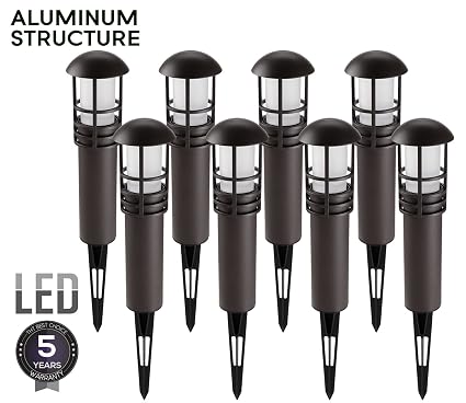
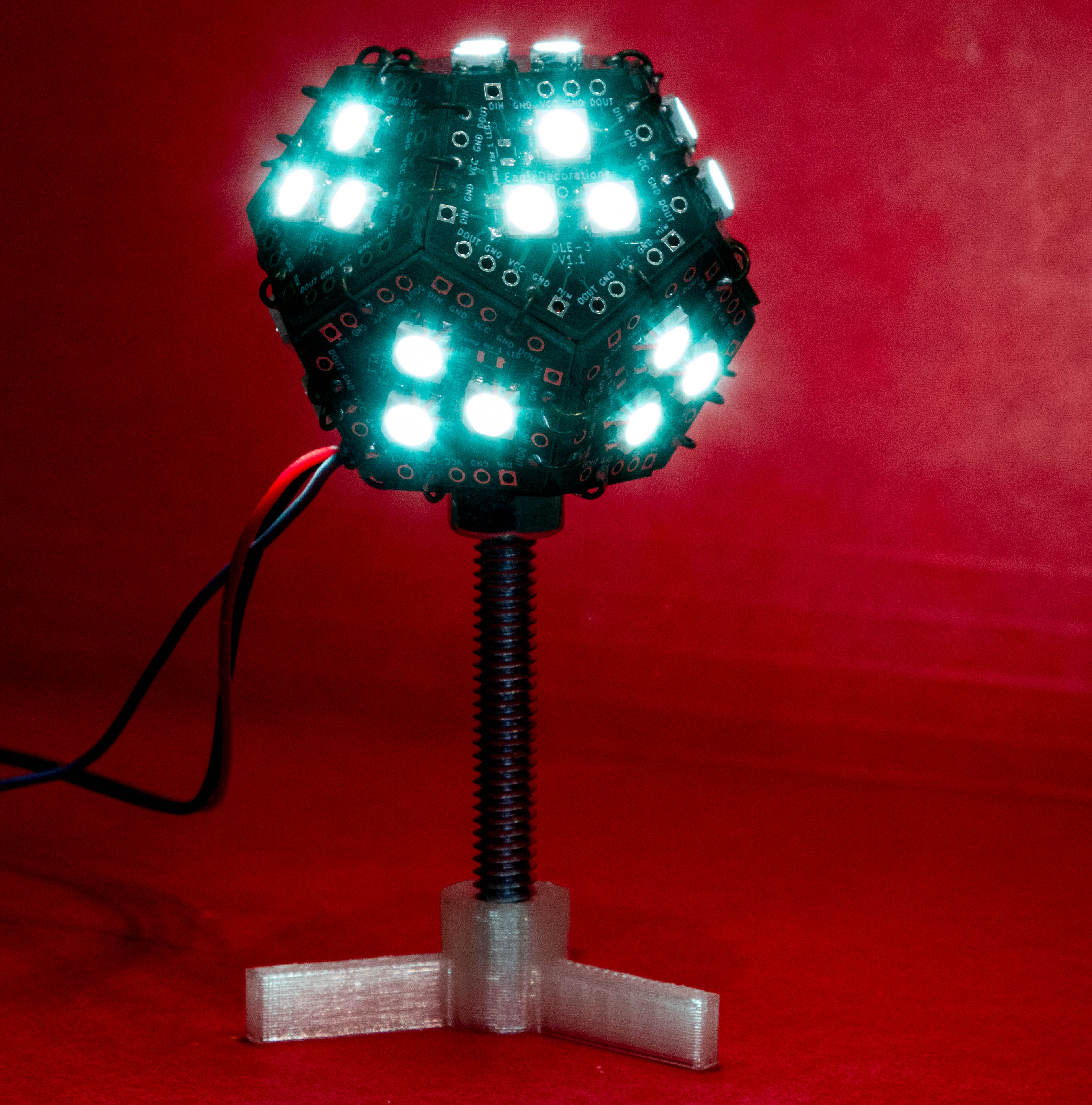
I have a product that I’ve just started selling; it’s a LED globe/Soldering challenge kit that looks like this:

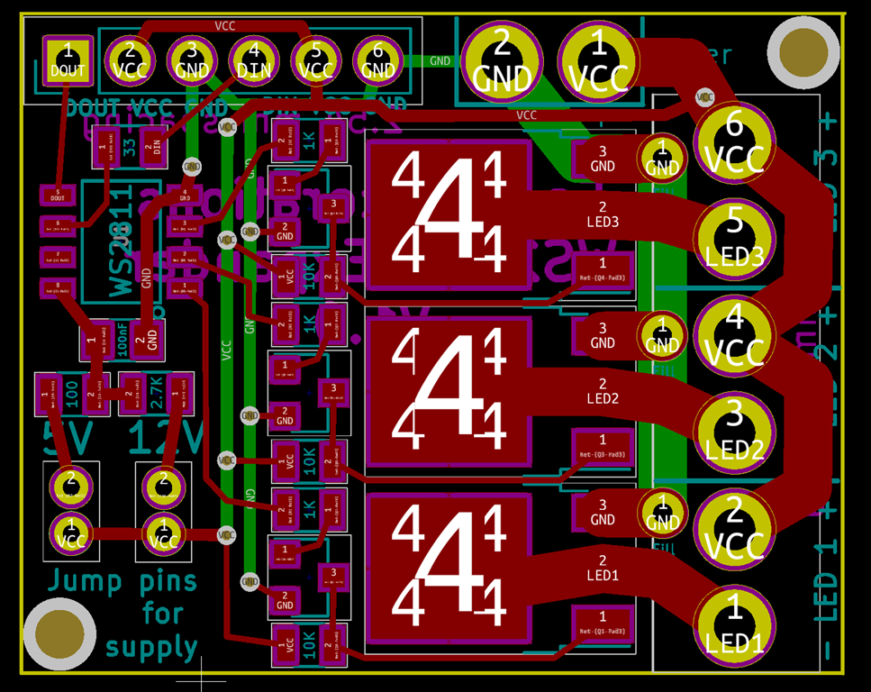
It has a PCB that looks like this:

image

For my first run, I needed to make 10 kits, and each of them has 12 of these boards, so that’s 120 boards.

I’ve been hand-soldering the prototypes, but it takes quite a while and my eyes aren’t as good as they used to be. I just built a reflow oven based on the controleo3 kit so that I can reflow in cases like this.

Which means I need a stencil. I could easily just order one up, but that means I’m going to have to align this tiny stencil with the board 120 times. Doesn’t sound like fun…

What we need is a way to apply solder paste to a set of boards in one shop and make it repeatable. In the woodworking world, that would call for building a “jig”, or perhaps a “fixture”. Which is what this post is all about; we’re going to use a laser cutter to make all of this oh so much easier.

Teaser photo

Here’s a teaser photo of what we’re going to build:

IMG_9248


Get your board outline and paste mask in SVG format

Since I’m doing my design in Kicad, this was really easy; just go into your design, click the plot button (like you would to create Gerbers), choose the F.Paste and Edge.Cuts layers, and set the plot format to SVG. That’s it.

Well, actually, you should probably modify your paste cutouts to be a bit smaller than they are by default; see this excellent reference for how to do it in Kicad.

If you are using a different package for your design, search online for how to make stencils from it; it will tell you how to export.

Create a combined image in Inkscape

The export give us two separate files; one has solder pads, and the other has the board outline. The first step is to combine them together.

Open both images in Inkscape. Change the color of the edges to blue and the color of the pads to red. We do this so we can control which ones get cut and which ones don’t in the laser cutter.

You do have access to a laser cutter, right? Because if you don’t you’re wasting your time.

Anyway, that gives us two instances of Inkskape:

imageimage

We now need to combine those two together in another image.

Create a new document in Inkscape with File->New. Go to the pads Inkscape version, do a Select All, then a copy. Switch to the new document, choose edit->paste in place.

Repeat the operation with the edge cut Inkscape version.

If your are of true character and have a pure heart, you will get the following:

image

Edit->Select All, then Object->Group. That puts this all together into a single object.

Save the document away with a catchy name like “Combined”. We now have the image for a single board.

Duplication

We now need to create an array of objects; in my case, it’s going to be an array of 4 wide and 3 high. We’ll start with the four:

  • Select the single object.
  • Paste it three time. Line them up approximately. It doesn’t matter like this.
  • Bring up the align and distribute menu. You will never find the icon to do this, so try CTRL-SHIFT-A. Hover around until you find a icon that says “align top edges”, and pick it.
  • Distribute the empty space using “make horizontal gaps between objects equal”.
  • Mine looked like this:

    image

    Those are way too close together for me. Undo the distribute, move one of the edge ones out, and redo the distribution.

    image

    That’s better. The actual spacing is up to you. Group them together and save.

    We’ll do the same thing for the rows; create two copies, align the left edges, and then distribute:

    image


    Save. Looks like we’re done, right? Not quite, there’s one more thing to add:

    Indexing

    This will work fine, but we would have to hand-align the stencil with the boards, and that’s going to be a bit of a pain to do. What I want is a way to make it repeatable.

    The secret is pins. Pins, I say!

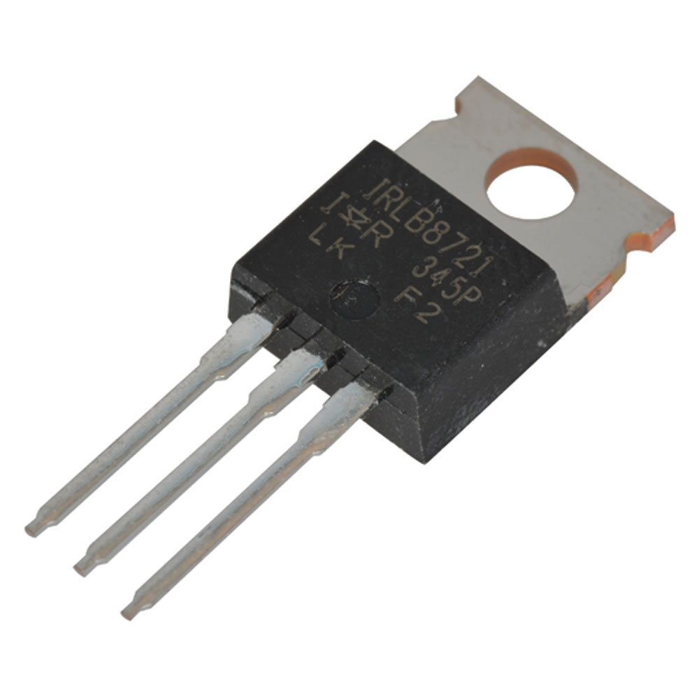
    A trip to my local hardware store yielded two 5mm shelf support pins. They are likely longer than I need and I might cut them in half for my usage. They look like this:

    image

    We are going to use them for alignment, which means we’ll need some 5mm holes.

    Flip back to inkscape, and draw a circle. Pick the selection tool, and up under me menu bar, you’ll see the width and the height. Set both to 5mm:

    image

    Set the fill color to full green, set the stroke color to black, flip over to the stroke style, and set the width to 0.1mm. It should look like this:

    image

    Put this one to the upper left of your objects, copy it, and put the second object to the upper right. It should look something like this:

    image

    Note that it doesn’t look that great. That’s okay, we will fix that now.

    Draw a rectangle from one corner of your objects to a point spaced away; this will be the pin location. Something like this:

    image

    Then drag the circle so that it is at the corner:

    image

    I call this “using a gauge block”. Move the rectangle to the other corner and use it to align the other pin as well, and then delete the rectangle. They don’t have to be symmetrical for the technique to work, but I like things to be regular.

    I ended up with this:

    image

    Why so many items and so many colors? We will use them in the cutting process.

    The jig that we created will be a sandwich of different materials; from bottom to top they are:

  • On the bottom will be a piece with only the peg holes cut into it; we will use the black circle outline for those cuts.
  • Next up we will have a piece with the peg holes and the edge cuts, so we will cut both black and blue.
  • Finally, for the top, we will cut the actual stencil; it will have the circles cut for alignment and the solder pads.
  • There’s a bit more complexity than that; I’ll talk about it when I get to the actual cutting.

    Materials…

    The goal of making the fixture is to make laying down the solder paste easy, so the materials need to be chosen carefully.

    My PCB house says that they material they use is 1.6mm thick. I don’t trust material thicknesses, so let’s check:

    IMG_9234

    That’s pretty close, just a 0.04 mm thicker than I expected.

    For the main parts of the fixture, I needed something that was fairly rigid, fairly cheap, and the right thickness. I thought about hardboard but decided to go with what is called “chipboard”; I’m not sure why it is called chipboard because it’s just very compressed cardboard, the kind you find at the back of tablets of paper.

    After looking it locally in vain, I ended up heading to Amazon, where I came across this:

    Grafix Medium Weight Chipboard Sheets, 12-Inch by 12-Inch, Natural, 25-Pack

    Grafix Medium Weight Chipboard Sheets, 12-Inch by 12-Inch, Natural, 25-Pack

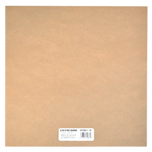
    25 sheets was more than I needed by about 24 sheets, but it laser cuts well and is decent for prototypes.

    The thickness isn’t listed in the specification, but that was one of the questions asked, so I looked at the answers and found that is was:

  • 1/16th of an inch at most
  • .057” (1.45mm) (from the manufacturer)
  • Almost exactly 1.5mm per board, determined by measuring a stack
  • 2 mm
  • It’s nice to have some many helpful answers. I could probably make most of those work, so I ordered it. It showed up, and what did I find?

    IMG_9233

    So, the correct answer was “none of the above”. It is notably a full 0.1mm thinner than what the manufacturer says. I’m not sure that just means there is more variance than the manufacturer says or they are just going thinner. Luckily, I can work with that thickness

    For the actual stencil, there were a few choices. You can cut them out of Kapton or out of Mylar. I went looking for Kapton in the common stencil thicknesses of 3 or 5 mil and didn’t find anything that looked good and cheap. So, looking at Mylar led me to Amazon, where I found 4 mil mylar, also in a package of 25.

    What is the mylar thickness?

    IMG_9237

    A quick bit of conversion shows me that the sheet is just over 3.8 mils thick, which is fine.

    Materials in hand, I headed out to my workroom where the glowforge lives to do some cutting.

    Some cutting remarks

    First up was cutting the mylar. The Glowforge has a significant bit of airflow to pull fumes out, and 4 mil mylar would blow right off the crumb tray, so I used ceramic magnets to hold it in place.

    One of the problems with mylar is that when you heat it up it tends to shrink. Since the holes I want to cut are rectangles, the laser head needs to stop at each corner, and at least on the Glowforge, it doesn’t do anything to the beam, so you will get a lot of power right at the corner. Maybe we could break the rectangles into two cuts and carefully manipulate the laser power, but I’m not that confident it would work. If you want to cut it normally, I would recommend trying low speed and very low power.

    Luckily, there’s another option. We can do a raster engrave of the squares and just ablate away all of the material in the middle. This avoids the “stuck in the corner” issue, and since the power level is fairly low and the start and stop is done by turning the laser on and off, there should be fewer issues.

    The right way to do this is to put a piece of paper under the mylar and figuring out what power and speed settings cut through the mylar cleanly but barely touches the paper. I grabbed some settings from the Glowforge Forums and used those.

    For the mylar, we are engraving the red paste mask part of the design and the green circles. The blue board outlines are disabled

    IMG_9228

    This is the first row being engraved. You can see that there is a little sloppiness in the outlines, but in general they are pretty much all the right size. Here’s the final sheet:

    IMG_9229

    The stencils look like what I expected and the 5mm holes look appropriate as well. Maybe this will work after all…

    Next up was cutting the top piece of chipboard with the board outlines. The board outlines are turned on in cut mode, the circles are switched to cut mode, and the paste mask is turned off.

    IMG_9231

    I previously did a proof of concept on this step, so I knew it was going to work. Nice clean cuts.

    And finally, the base cardboard piece. All it has is the circles, so it looks like the above picture with just the circles.

    Assembly

    Sandwich time!

    We start with the base.

    IMG_9239

    And then add in the 5mm pins. This posed a bit of a problem; the pins have a nice chamfer on the end so they didn’t stick into the cardboard very well. I solved this by cutting one of the pins in half with a dremel and an abrasive wheel. I should also note that at 4.96mm, they are just slightly undersized.

    IMG_9240

    So, it turns out that the 5mm holes aren’t quite 5mm in size; they are just a bit smaller so I need to force them in a bit. A friction fit is good, but a forced fit is less good. This is exactly the sort of stuff you learn if you do test cuts. Well, perhaps version #2…

    Adding in the board layer, which aligns quite well with the bottom layer. And the boards fit with just a little bit of movement, which is just about perfect. They are proud (above the surface) by about 0.3mm, which I determined by math. That will probably be okay, but if I want/need it to be closer, I can easily shim it out with some mylar, which at 4 mil is almost exactly 0.1mm thick.

    IMG_9241

    The moment of truth. Adding on the mylar layer. The mylar holes are also too small, perhaps more too small than the cardboard.

    IMG_9242

    What sort of result did we get? It mostly looks pretty good. There is a tiny bit of bowing in the mylar, which I think is due to the “too small holes” part, but it’s probably good enough right now. The alignment is offset a bit but it’s certainly usable:

    image

    Revision #2

    The nice part about building a jig this way is that the materials are cheap and doing another set of cuts doesn’t take much time, so it’s easy to do another revision.

    My first goal was to fix the circles so that they better matched the pins. Since I set them to 5mm explicitly, I figured I’d need to make them a little bit bigger. So, I opened up the design in Inkscape, selected the circles, and what did I find?

    4.95mm

    Huh? I honestly set them to 5mm, but now they are smaller.

    A bit of experimentation revealed what was going on. I am used to working in Visio where the dimensions are inherent properties of the object, so a circle that is 5mm in size is always 5mm in size.

    Inkscape is different. When you way that a circle is 5mm in size, you are setting the outside diameter, and that includes the line width. So, if you set the size of the circle and then change the line width to be thinner, your circle will no longer be 5mm in size. More like 4.95mm.

    Discovering this made me happy, as it meant that the bad fit was from something I understood, not something I did not understand.

    That was a really quick fix, and I cut the new pieces and put the sandwich together. This worked much better; everything went together much easier, and the alignment was better:

    IMG_9245

    Looking closely at the entire stencil, the errors look pretty random. It’s by no means as nice as the commercial stencils I’ve had cut, but it seems serviceable enough.

    I did want to deal with the spacing issue so I could get the board thickness a little closer to the fixture thickness. It turns out that 4 mil is almost exactly 0.1mm, so I cut a spacer as part of the previous revision. Here’s a crappy picture of my first attempt (the stencils are really hard to take pictures of):

    IMG_9246

    That is what happens when you try to cut mylar with high power; the beams stays on at the corners and totally blows it out. I *thought* this would still be usable, but all that melted mylar globs up and is way thicker than 4 mil.

    I cut a second version as part of the revision, using the lowest power that would work.

    IMG_9247

    That is definitely much better, but when I grabbed my micrometer and measured it, it turns out that the mylar melts a bit where it’s cut and the edges are about 0.2mm thick. Since I was hoping for something like 0.3mm total, just using this spacer should be sufficient.

    First pass with solder paste:

    IMG_9248

    And the resulting boards. It was mostly good enough; needed a bit of touch-up for a couple.

    IMG_9249

    LEDs and decoupling capacitor added:

    IMG_9250

    Into the oven:

    IMG_9253

    And all done:

    IMG_9254

    The reflow worked well; 11/12 were fine at the start, and I replace one LED to fix the others.

    IMG_9256

    Round 2

    Round 2 was more of a production run. I changed my technique so that after putting the paste on, I would peel the stencil up and then separate the layers to let the boards fall out the bottom. This worked pretty well. I did 9 rounds plus 4, or 112 boards total, which used up most of my LEDs. Two rounds in the oven, and I had 111 functional boards.

    I really need to build a new test rig; the current one only tests 3 at a time and it’s a pain to load them.

    Summary

    I’m quite pleased with the way that the jib turned out; I pretty much works exactly the way I had hoped, and I can apply paste and populate a set of boards in about 10 minutes.


    DLE (Globes of Fire) Part 5 – First Board!

    When a new telescope is completed, one of the big milestones is known as “first light” – the first time that the telescope is used as it is intended.

    Now that I am the proud owner of a reflow oven – a modified Black & Decker toaster oven fitted with Whizoo’s Controleo3 reflow oven kit – and I have a new version of my boards back – it’s time to think about how to build these things in a reasonable way.

    The plan is obviously to switch from hand-soldering to reflow. To do that, the first thing that I need is a stencil that I can use to apply solder paste. Thankfully, kicad makes this really easy; you can modify the solder pad tolerances in the program, and the pcb editor can write out SVG files (thanks to Rheingold Heavy for this post). If I have the pads, I can easily cut a stencil, likely out of mylar because it’s a bit cheaper than Kapton is.

    That would give me a way to do a single board if I could hand-align it closely enough. But each of the globes needs 12 of these boards, and hand-aligning is a pain.

    So… what my real plan to do is to cut holes in a piece of hardboard (or cardboard) that will hold a number of the boards (12 or 24) and then a matching stencil. If I align the stencil one, then I can put solder paste on all of them.

    IMG_9223

    So, here’s the test. I took the pad svg and the board edge svg, joined them in inkscape and then cut them on the glowforge. As you can see, the boards fit perfectly into the cutouts, and the solder pads cut correctly. Next I will need to do a better version of this, with different colors for the pads and board edge so I can turn them off and off when laser cutting. I’m also probably going to cut holes for some posts that will give me registration between the board with cutouts and the stencil.

    You can also see the first two boards that ran through the reflow oven. I did the solder paste without a stencil and I also skipped baking the LEDs since they showed up in a factory-sealed pack and have been sealed since, and both boards came out fine. And a 10 minute reflow cycle is a lot quicker than hand soldering…


    Provisioning and using the ESP8266 controller

    The ESP8266 controller is preprogrammed with the ability to connect to your local wifi network and be remotely controlled.

    Provisioning

    Initially, the controller does not know how to connect to your network, so it sets up its own network. Here is how to set it up:

  • Using your phone/laptop/tablet, connect to the network named something like “EDP_1002170403”. The password is the same as name of the node.
  • One you are connected, open up your browser and navigate to http://192.168.4.1. That should enter the provisioning page. Enter the SSID of your wireless network and the password, and click on connect.
  • If everything is working correctly, that will connect to your wireless network. You can find out the IP address by looking for the “EDP_…” name in your browser’s host table, or you can hook the esp board up to your computer and watch what it writes out the serial port when it boots.
  • Controlling via http

    You can control the LEDs via http by sending textual commands to controller. The format looks like this:

    http://[ip address]/message?content=[message]

    Controlling vs UDP

    If you want realtime control of the LEDs, http may have too much latency, which may result in unexpected pauses. The controller also supports communicating through UDP.

    To connect via UDP, use the same IP address and pass commands directly. The internal controller code runs at 100 Hz; if you drive with UDP messages at 60 Hz everything should just work great.

    Supported Messages

    All commands are three letters long, followed by another character (the examples use an underscore (“_”), followed by numeric parameters.

    The following commands are supported:

    Alternate

    Alternate between two colors.

    alt_r1,g1,b1,r2,g2,b2,time

    r1, g1, b1: the rgb values (0,255) for the first color (0-255)
    r2, b2, b2: the rgb values for the second color
    time: the time for each color

    Example: alt_0,100,000,000,000,000,250

    Blend to

    Blend from the current color to a specified color

    rgb_r,g,b,time

    r, g, b: the rgb values (0,255) for the new color
    time: the time for the blend

    Example: rgb_255,255,255,1000

    Color rotate

    Rotate through a bunch of different colors.

    col_speed,brightness

    speed: the speed of the rotate
    brightness: The brightness of the colors

    Example: col_5000,200

    Flash decay

    fdc_decay,min,max

    decay: the speed of the decay
    min: the minimum pause before the next flash
    max: the maximum pause before the next flash

    Example: fdcx250,10,500

    Full control

    Full control is used to control the color of all the leds directly.

    ind_chunk,data-bytes

    chunk: the number of leds to apply each set of data to.
    data-bytes: colors express as two digit HEX values in the format RRGGBB

    Example: ind_011,000044440000004400

    Each color in data-bytes will apply to 11 LEDs. The data-bytes contain 3 color values:

    000044 – a blue value
    440000 – a red value
    000044 – a green value

    Save

    Save the current animation so that it will use that animation when rebooting.

    s

    Set pixel count

    Set the number of pixels that the controller will use. This will result in a reboot of the controller.

    n_count

    count: the number of pixels

    Example: n_13