Browsing posts in: Electronics

DLE (Globes of Fire) Part 4

It’s been very long since my last update, and a fair bit has happened.

Hardware:

I did a rev 1.2 of the board and sent them off to allpcb for a small run (10 IIRC, so 120 of the LED boards and 15 of the end boards).

The boards showed up quickly, and didn’t work. Well, two of the LEDs worked sometimes, but the third would not.

Clever me, I did some led moving and I managed to route the VCC line for LED #2 right across the data out pad when I did some moving. I could break the pad by hand and get them to work, which through trying to be quick led me creating a circuit that would work for all the colors except white because I didn’t break the trace completely. Which led me to think a new real of LEDs was bad and waste a couple of days trying to track down what was going on.

I took the opportunity to do rev 1.3:

image

I bumped the VCC and ground tracks up in size, redid the VCC routing, and just generally cleaned things up to be nicer. I also added (finally) a 100 nF decoupling capacitor to the right of the #1 LED, which should help eliminate glitches in the future.

I spun a small verification order (3) through OSHPark because it was only $5, and those worked great. After that, I pulled out my little list of material costs, went back to reprice the PCBs, and found that JLCPCB would do my full first order for $83 delivered, which was about 30% less than the $120 I had written down. Given the temporary nature of PCB special deals, I put that order in, and today found this on my doorstep:

IMG_9215

Well, technically they were in a *box* on my front porch. That is 600 of the LED facets in the two bags at the top and 50 of the top facet in the small box. And the two pretty purple boards are the test ones from OSHPark.

Assembly

I’ve gotten pretty good at soldering the LEDs on the facets, but my plan all along was to reflow them. Towards that, I picked up a few things:

That’s a nice little Black & Decker TO1313SBD toaster oven.

And:

That’s a Controleo3 toaster oven conversion kit. We’re going to hot-rod that oven, adding a full computer control to it (the blue board on the left), add an extra heating element, a lot of insulation, and even a servo to open the door.

All of this will give me a reflow oven; you can put a board with solder paste and components on it, hit a button, and it will heat the board at a certain rate until the solder melts and then cool them down at an appropriate rate. It’s going to live under the garage near the laser cutter, and my guess is that I’m going to need a bit of ventilation for it.

Firmware

I am at what I think is the V1 firmware, for approximately the third time. This took a whole lot of time and effort, with the usual fun of running two different codebases on two microcontrollers connected over USB.

Provisioning

The first time setup for IoT devices can be a bit of a pain, as they have to get your wireless ssid and password. In playing around, I found that iOS doesn’t let you enumerate wireless networks or change connections programmatically, which meant it might be a real pain to set up multiple nodes by hand.

Then, I had a small bit of insight, and realized that I already had a device that could easily enumerate all the wireless networks; the ESP can do that an I already had the code because I needed it for testing. It was merely a matter of grafting it onto the existing code.If you connect to the network for any node and give it an SSID and password, it will verify that it works and then pass it off to all of the other nodes so that they can auto-configure. That code is all done, and it’s pretty cool to watch because the current firmware shows the state of the connection by flashing. Okay, maybe that’s only a little cool.

Animation

I wrote a few of the simple animations that I want; some color rotations, a flash and decay animation, and a blend from the current color to a new one.

I also wanted to be able to go fully to the metal and control every LED remotely and quickly. That led me to a better Http server for the ESP, a brief flirtation with TCP, and finally an implementation based on UDP. The server is fast enough that you could send the data for all 33 leds 500 times a second and it would work; it is currently constrained to 100 Hz because that is the speed the animation loop runs at, and I expect that for real applications sending data at 60 Hz would be fine.

I am particularly happy with how the command processor worked out; the implementation is nice and clean.

The wireless information is stored in permanent memory, and it is also possible to store the current animation so that it will resume on startup.

Software (app)

I want to have an app to control all of this. It needs to support both Android and iOS, which made Xamarin the logical choice; I can support both and I can write C# code which is a huge plus in my book.

Like many open-sourcy software, it can be a real pain at times, but I’m able to build an app that deploys to my phone and debugs, and that’s a decent first step. I’m working on network discovery right now; once the provisioning is done, the app needs to enumerate all local ip addresses and see if one of my controllers is hiding there.

And I’m using Xamarin Forms, which is built on top of XAML, which I guess is an advantage since I did XAML professional for a fair bit, but it’s a bit of a mind-bender as usual.

I wanted to do something different for discovery, so I wrote a graphical pinger. Here’s a video.

The app still needs a lot of work; it needs a way to do the initial provisioning, a way to list the different animations it can do, a color picker, etc.


Givin’ the dog a bone–USB charging station part 2

One of the realities of doing CAD work is that the real world sometimes intrudes…

Your laser cutter – for example – is limited to cutting a given size of material, and only in one plane. And it isn’t a perfectly thin cut, there is a little width to the laser beam.

For router-based machining, one of the problems is that the cutter is round, and often the cuts you would like to make are square. Here’s an example:

Image result for cnc dog bones

The part on the left is what you designed, and the part on the right is what you got when you cut it. There are a few approaches to deal with this; you can cut the corners out with a knife or saw, you can just pound the parts together and hope the material yields, or you can change your design so that the corners are cut out. It looks like this:

Image result for cnc dog bone examples

Hence the name “dog bone”. With the Shaper, there are a few ways to do this; you can either modify your design to include the dog bones, or you can do them on the tool, one at a time, kind of by hand. Since there are hundreds in this design, doing them on the tool did not seem very exciting.

There is an add-in for Fusion 360 that does dog bones, so I installed it and tried it on a few designs. Like lots of freeware, it’s a bit challenging; you either have to pick every corner where you want the dog bone, or you can let it pick the corners that need to be modified but this only works if the corners are vertical.

Oh, and it takes a long time. A *long* time. Like 5 minutes for a panel with just a few cuts if you mark them by hand, or 20+ minutes for one with lots of holes (19) where it figures out which corners to modify. This is made much more annoying because Fusion 360 does something that I thought wasn’t supposed to be allowed under Windows UI guidelines any more; the status bar that it shows brings the window to the foreground and selects it. Since this is happening about every second, you can’t do anything else on your computer while the dog-boneification process is underway. Which kindof gets in the way of making good progress, since you need to go and do something else.

About this time I needed to get some wood for the shelf, and I needed to know how much and how I would arrange it the cut pieces on the board. I found this tutorial to be very useful in understanding how to do that, and ended up with a nice layout on a 24” x 48” sheet that used a bit more more than half of the space.

Went to add the dogbones by selecting all 13 pieces in the and kicking off the add-in. An hour later it was still running. Two hours later is was still running, much more slowly. Left it overnight and came back to the autodesk crash dialog.

About this time I was really thinking of just using the Glowforge and forgetting about dogbones, but the whole point was to use the shaper, so I pressed on.

Went out for lunch, picked up some stock (birch plywood that was 4.7mm thick), rolled back to my 3-d layout, set the thickness of the stock, and went through and did each of the dogbones by hand-selecting each corner. After that was done, I ran the Fusion 360 plug-in for the Shaper Origin, which generated SVG files that I uploaded to their website (you can use a USB key if you’d rather). I was going to do the bottom part of the design; the last wide shelf and then the pieces that hang the hub underneath that, four pieces in total.


image

At some point, Fusion lost the material selection for the one piece, and I was too lazy to fix it.

IMG_9171

Here is the setup. Sitting on the router table portion of my BT3000 table saw, I have an extra ikea shelf (melamine and very flat), a sacrificial piece of MDF on top of that (you need to cut just through the material), and then the birch plywood on top (that piece was about $8). Across the wood you can see the “shaper tape”; this is how the vision system on the router knows where it is. The basic process to cut is:

  1. Move the router around so that it locates all of the domino-shaped shapes on the shaper tape.
  2. Load a design (in this case, from the online pieces I uploaded)
  3. Set the cut parameters (the size of the cutter you have in the router (1/8” in this case), how deep you want to cut on this pass (I did two passes, one at 0.125” and one at 0.2”)
  4. Do a “z – touch” so that the router knows where the top of the material is and can therefore judge depth.
  5. Move the router so that the line you want to cut is inside the circle.
  6. Turn the router on (using the physical switch on the head)
  7. Press the cut button (green button on the right handle), and wait for the bit to plunge into the work.
  8. Navigate the router around the cut.
  9. Press the retract button (orange button on the left handle), and wait for it to retract.

At that point, you can move to another cut that needs to be made or change parameters and recut the same line (deeper, for example).

This worked really well, except for two issues. The first was that on my second cut, something went wrong, and on the cut, the router plunged the bit as deep as it could and then the software crashed (you can see the burned hole near the bottom of the workpiece). I had to turn off the router, pull it carefully out, and cycle the power on the shaper to get back. The second was my fault; I cut all the way through an outline before forgetting that the piece I cut had a cutout. Oh, and the software crashed again when it was just sitting there; the image on the display is a static one before I moved it to make the picture nicer.

And the result is…

IMG_9172

IMG_9173

What do we see? Well, the first thing you’ll notice is that there is a lot of fuzziness on some of the cuts. The shaper uses an upcut bit, so that’s pretty common. The fix is to do the first cut at a bit of an offset back from the line and then do the final cut without the offset. Overall, the lines look really straight, which is remarkable given that a human is moving the router around.

What else do we see? Well, the joints don’t look very good, and there is a distinct lack of dogbones on them.

It turns out that I outsmarted myself. One of the tricks with dogbones in wood is to set the cutter size slightly smaller than the actual size of the cutter; that makes the dogbone a bit smaller but it still works since the wood has a little give to it. But… the Shaper knows the size of the cut you are asking it to do and the size of the cutter, so it just avoids cutting the dogbone path. I cut them by hand with a utility knife, but I was short of time so this is the result I got.

Finally, a couple of action shots with the hub in place:

IMG_9174

IMG_9175

Up next is to redo the dogbones for the remaining pieces *again*, and the cut them using the offset to see if I can get nicer joints.


WPC Driver board Upgrade

I finished the upgrade of my WPC driver board today. It was fairly simple despite Williams using a crappy circuit design; instead of using vias to carry power from one side of the board to the other, they rely on component leads to do that, presumably to save cost.

If you do this yourself, after you remove the component make sure to tin the ring on the component side with solder and overdo the amount of solder you use if you can’t see the component side; I had to redo several of the big capacitors because they had great solder joints on the bottom but not enough solder to grab onto the other side. So, on those components, jam more solder in there than you would normally do, and I also recommend grabbing the schematics, an ohmmeter, and checking for continuity through the hole.

WCS Power Driver Board Voltages

I measured the board voltage for future reference, both with only the input power connected to the board and the game in attract mode, using a quality Fluke voltmeter.

AC is measured to look for poor filtering by the large capacitors on the board; as the capacitors degrade there will be more AC present on the voltages.

Test point Input DC Input AC Attract DC Attract AC Description
TP1 15.83 0.002 13.8 0.1 +12V filtered but not regulated
TP2 5.02 0 5.01 0 +5V regulated Digital supply
TP3 12.03 0 11.7 0 +12V regulated digital supply
TP4 0.393 0.6 3.80 0.06 zero cross
TP5 Board ground
TP6 77 0 76.2 0 +50V for solenoids, flippers
TP7 22.26 0.003 21.8 0.01 +20v flash lamps
TP8 18.52 0 13.9 – 15.1 0 – 2 +18 to lamp columns


WPC driver board issues

My WCS 1994 is having some issues; the DMD display is showing static and now the game is behaving strangely.

I’ve been using the guide here, but I’d like to share some other data I’ve gathered since I didn’t find it elsewhere.


Test point Working DC Working AC Problem DC Problem AC Description
TP1 14.7 0.63 13.5 0.08 +12V filtered but not regulated
TP2 4.93 0.01 4.97 0.001 +5V regulated Digital supply
TP3 11.92 0.008 0.758 0.122 +12V regulated digital supply
TP4 0.37 0.63 3.62 0.06 +50V filtered
TP5 0.03 Board ground
TP6 73.2 0.2 – 0.8 75.1 0.01 +50V for solenoids, flippers
TP7 21.7 0.09 21.6 0.04 +20v flash lamps
TP8 15-17 0.2 (ish) 11-14 0.8 (ish) +18 to lamp columns

“Working” values come from my Twilight Zone (working), while “Problem” ones come from my WCS (not working).

What can we tell from this?

Well, a few things. The obvious issue is TP3; it is less than 1 volt when it should be around 12 volts, and it’s letting a lot of AC through at all.

Time to pull out the schematics.

image

Sorry, that was the best image I could pull from a PDF; the paper version isn’t much better.

Basically, we have power coming in from the left side, which should be a nice healthy 18volts (measured at TP8). It goes through two series diodes that will drop the input by a little over a volt, and then it goes to an absolutely-standard 78xx linear regulator circuit; a capacitor on the input, a 7812 (for 12volts) and a capacitor at the output. 78xx regulators are pretty robust, so let’s see if we’re using it correctly…

Like most linear regulators, the 78xx series has some limitations around input voltage; it requires about 2 volts of headroom to be able to give us the output voltage, so we should be looking for 14 volts coming in. We have 11-14 volts – it fluctuates because the lights are flashing in attract mode. That 11-14 volts isn’t enough to consistently give us enough voltage for the 7812 to give us a nice 12 volts.

So, we don’t have enough power coming in, so that is the problem, right? Well, not so fast. Based on what I know about the 78xx regulators, one would expect that if the voltage drops enough so that you don’t have a full 2 volts, you will see the output voltage slowly drop down.

I pulled out a 7809 and hooked it up to my variable power supply, and found that this was mostly true; the dropout voltage was about 1.2 volts (two diode drops). That means I would expect that the 7812 would put out less voltage but something close to 12V.

So, that suggests that we have two issues going on; we don’t have enough voltage coming in for the regulator to work and the regulator looks fried. That is supported by some data I had before this where the game was acting very weird and the voltage at TP3 was fluctuating all over the place. So, a new 7812, and it would be a good idea to replace the 1n4004 diodes and the electrolytic capacitors in this section at the same time, since this board is nearly 25 years old.

Looking at the input voltages at T8, note that there is a decent AC component in the DC voltage – about 0.8 volts. Back to the schematics:

image

This is also really simple; we have AC from the transformer coming in, going through a full-wave rectifier, and then there are two honking big 15,000 uF electrolytic capacitors. As these capacitors age, they are going to lose some capacity and have an increased internal resistance; both of those make them worse at filtering, so it’s time to replace those as well. It’s possible that the AC that they are putting out ended up hastening the end of the 7812.

It’s typical to replace both the capacitors and the bridges when the board is reworked, just to make sure, so I will probably do that.

I am a little concerned by some of the values I see on my TZ board; there are some indications that the caps there need replacement as well. I’ll do the WCS and then compare it to the TZ one.


DLE (Globes of Fire) Part 3

 The new boards arrived from allpcb.com. To recap, this, time I went with standard 0.1” (2.54mm”) header pins between the boards. I ordered some angled headers from the Amazon to use for the connections.

IMG_9061

After I populated 11 faces with LEDs, it was time for assembly. Here’s the first approach:

IMG_9063

The first concept was to wire the faces together with short pieces of header on the back. This worked poorly; it took a long time to hook them up and the angles were rarely right. The first half was technically done, but I was unhappy.

For the second half – and keeping in mind that prettiness was not a requirement – I decided to go with another approach. I would use angled headers on the outside, and just solder the pins together where they overlapped.

But first, I needed a better way to set the angle. The led to the following design in TinkerCAD:

image

And then a long session of setup to migrate my 3D printer from an absolutely ancient laptop to one that was merely old. I printed up a whole set of these, and then used them to hold the faces at the right angle for soldering. That resulted in this upper ring:

IMG_9068

The alignment clips on the right worked very well; it only took about 30 minutes to do this whole ring. And yes, it’s very ugly.

Time to hook them together, and then attach on the end face. These are attached with small pieces of header pin on the outside.

IMG_9069

Then it’s time to wire up the 5 volts, ground, and data, and take it out for a spin.

The first attempt was not successful; one ring lit and the other didn’t. A quick check discovered that the ground connection between the two rings was not functioning, so I added an additional connection. Which led to this:

IMG_9071

The driver is running some simple rainbow code, so each LED is a slightly different color.

Finally, adding on the requisite acrylic globe gives us the following:

Globe of fire from Eric Gunnerson on Vimeo.

Overall, I’m mostly happy. It would be nice if the header holes were a bit tighter on the pins, and I could clearly get by with 2mm or even 1.27mm pins. The 3d-printed alignment clips could use another iteration to make them easier to use.


DLE (Globes of Fire) Pt 2

A week or so goes by, and I get a package back from allpcb, so I started building one.

Each half has a ring of 5 pentagons plus one the end, so I started hooking 5 boards together:

IMG_9044

The WS2812 LEDs are only 5mm on a side, so the whole board is roughly 15mm x 17mm. That’s tiny, and frankly working on it was a huge pain. I did this, put the boards into a box, and closed it.

Then I came back the next day and decided to have another try. Rather than connect on the outside, I decided to use a much lighter wire and connect on the inside (back) of the boards. Here’s a set of 5 with VCC and GND hooked up:

IMG_9046

Yes, that’s some *ugly* soldering, but in my defense I’d like to note that the spacing on the holes is about 0.05”/1.3mm. This then gets folded into a ring. Eventually, we end up with the top and bottom:

IMG_9050

Next, those two are soldered together with wires to carry VCC and GND between halves, and you end up with this:

IMG_9052

Next was to wire through the data ports. Basically, it starts at one face at the open end, goes around that ring, goes around the lower ring, and finally travels to the bottom. Add in some hot glue to help hold things together, and put the LEDs on, and here’s the result:

IMG_9053

That is one ugly bit of construction, and it took a lot longer than I had hoped.

IMG_9055

After soldering a few hundred WS2812s, you learn how to do it without burning them up. On the left is one face from the 3-LED version that I tested to verify the layout.

V1.1

The first version was technically a success, but only because I so cussedly kept on. I was wondering if I could make something small enough to fit in an ornament ball, and the answer is “yes”, but you really don’t want to do it.

So, it’s practically a failure.

The biggest problem is the connection between the faces; the holes are too hard to solder, and using individually-cut wires is a pain…

So, I’m going to abandon the single-LED version (kindof – more on that later) and work on the 3-LED version. I started by going with standard 0.1” (2.54mm) header spacing, and the plan is to use angled headers. The angled headers will stick out to the side, and two faces are connected by soldering the ends of the header pins together. It’s going to look a big weird, but should be a lot easier to construct.

Here’s the old design and the new one:

image

Obviously, the big different is the connectors; they are much larger, though the overall design is only a big bigger. I’ve used the extra space to pull the LEDs a bit farther apart because trying to hand-solder the LEDs in the first version was a difficult. And I added a little bypass jumper; if you solder a wire (or better, a 0805 zero-ohm resistor) across those pads, you can omit the bottom two LEDs and things will work fine.

If you read backwards, you might see that it says “Dodecahedral Light Engine” on the back, which is the new name for the boards.

A fully-populated DLE will features 33 LEDs, pull 2 amps @ 5V with everything on white, and put out quite a bit of light.

I need one more design review pass before I send this one out to have boards made.


Globes of Fire!

The parts for the new controller have started trickling in, but until they all show up I’m a stuck there, so I’ve been thinking in other areas.

In the olden days – pre LED – I had a number of the 50 or 100 light globes in my display:

See the source image

I liked them for their intense burst of light, but the ones I had gradually died, and I haven’t found a replacement.

So… I got thinking again about options. When I built my Animated Snowman, I used WS2182 leds on the faces of 3d-printed dodecahedra. It worked fine, but the hand-cabling was a pain:

IMG_8435[1]

Using the acrylic lamp globes worked great, however. They are cheap, easy to get, and fully waterproof. I just needed a better way to get the LEDs in place.

One of the nice things about dodecahedra is that the faces are all pentagons. I remember a hack-a-day article a couple of years ago when somebody built one by soldering pc boards together, so I decided to do a design of that what that might look like:

image

The concept is that any face can hook to any face. You wire up the ground and VCC connections on all faces to give rigidity to the dodecahedron, and then wire up the DIN and DOUT connections from face to face in whatever pattern makes sense.

This design gives me 12 LEDs (well probably 11, since the top or bottom one will be used for support) in the space of about an inch, so that would easily work in the small acrylic balls (6”, or 4” if I can get them).

Of course, why do one LED per face when you can do 3:

image

Same concept as before; hook up DIN from another face, it will chain through all three LEDs and then head out through DOUT.

This board is roughly an inch in size, so the resulting dodecahedron will be around 2” in size. That will give us 33 LEDs and live up to the title of the post, but it may be overkill, which is why I’m going two versions. I’ll drill a hole through the 12th face and use a threaded rod and nuts to mount the DLE (Dodecahedral Light Engine).

I need to do some design cleanup and then send off for a run of these to see how they work.


Snowflake–custom controller

The Adafruit Huzzah was a nice starting point for the snowflake, but it’s both more expensive and not well-tuned for what I need. To drive the WS2812s, all I need is a single output, and I don’t need dedicated buttons on the board.

I went back and forth on whether I wanted to do two controller boards – one that used the ESP8266 and another that used a cheaper AVR, but the ESP can be had so cheaply that it hardly seemed worth it. I considered a number of different ESP modules – or even building directly from the ESP8266 and adding flash, but the ESP-12 is pretty cheap and it has FCC certification (or is claimed to, at least).

So, basically, I took the Huzzah design and looked at it in Eagle, and then pared off things that I didn’t need and did my design in KiCad. It currently lives here.

The design is pretty minimal; it has a small 3.3 volt linear regulator to power the ESP (I used the same SPX3819 as on the Huzzah), appropriate resistors to put the ESP in the right state, diodes to handle level conversion between the 5V world and the 3.3V world and two headers. There’s a 6-pin programming header that has power, serial connections, and the reset and GPI00 pins on it, and there’s a three pin header for operation that has 5V and GND in to power the board and the data line out for the WS2812 string. Simple and straightforward. There will probably be another version with another sensor; I’m going to need a way to reset these things to handle wireless setup and my new design will be fully encapsulated, so I’ll probably do something magnetic.

Here’s the schematic:

image

Once I had that, it was off to do the PC board layout. That is really my favorite part of the process; to go from a set of random components on the board to something functional (and perhaps even elegant) is a rewarding process. Here’s the layout.

image

I decided that I wanted both sets of connectors at the bottom and the ESP-12 at the top. Basically, the jacks are at the bottom, the 3.3V supply is in the middle, and the resistors, diodes, and LEDs are on the sides. All of the small components are 0805 sized, since I wanted something that I could hand-solder if necessary, and those will also reflow reasonably well if I want. Given the need for two jacks and the space they take up, there’s not a lot of margin in going smaller at this point.

One of these times, I’m going to do snapshots of what it took to get to a decent layout.

The PC boards got finished and sent out to AllPcb.com, who sent me 10 (actually, 11) copies of the board for a total of $5.49 with about a 7 day turnaround. I don’t understand the economics of how that can be profitable, but I’m not going to complain right now.

Initial guesses at the overall costs for the controller:


Part Price
ESP-12 Module $1.78
3819 regulator $0.06
Other parts $0.11
PC board $0.50
Total $2.45

No labor in there yet, but it’s just a matter of putting the parts on there and reflowing them. It should be pretty quick, and I’ll check to see what it would cost to outsource it as well.

The boards have showed up, but I was too cheap to pay for fast shipping of the other components, so they’ll trickle in and then we’ll see if my design works.


Snowball pricing analysis

I’ve been thinking about maybe selling the snowflakes – or a variant of the snowflakes – commercially. Pursuant to that, I did a few calculations on parts costs.

Here’s what it would take to build the prototype in volume (say, 100 units):


Part Price
PC Boards $2.04
55 WS2812 LEDs $3.72
Adafruit Huzzah $7.96
Acrylic $4.07
Printed separators $1.00
Labor @$13/hour $26
Total $44.79

The labor is frankly a bit of a guess; it’s probably quite a bit worse than that.

Assuming I wanted a 50% margin, that would put the retail cost at about $90. The snowflakes are nice, but I’m not sure they are $90 nice.

To reduce the price, we need to look at the places that are the most expensive. Clearly, labor is a problem, so making the design easier and more robust to assemble is going to be critical. And the cost of the Huzzah is a big part of the parts cost, so coming up with an alternative that is easier and cheaper to use makes sense.


Snowflake Final

The snowflakes – five in total – have all been finished.

Well, mostly finished… there are three animating themselves on the gutters of the house right now, while the remaining two (which were on the house until this afternoon) are waiting for their waterproofing to cure.

This post will cover a lot of ground, since I missed a couple of updates along the way. 

Assembly

When we last left our story, we had a PCB in the snowflake form and some laser-cut pieces of translucent acrylic that go on the front.

The next step was to put the LEDs on the board. My hope had been that I could use the hot air rework station to reflow all the LEDs, but a bit of experimentation showed that I was melting the LED cases and hand soldering was faster, so I went that way. I think a cheap reflow oven is in my future.

I used the following approach:

  1. Add solder to all the solder pads on the snowflake (55 * 4 = 220 of them).
  2. Carefully hold an LED in the right position, and touch two of the pads to tack it in place.
  3. Press down hard on that end of the LED, and touch each pad until the LED sinks down even with the level of the board at that end. .
  4. Repeat on the pads at the other end of the LED.
  5. Reheat the first two pads to get rid of the stresses induced when the second end was dropped down.

That was mostly straightforward, except it turns out that if you put the LEDs in backwards, they turn into HEDs – Heat Emitting Diodes – and you get to remove them and put new ones in their place. I put my new hot air rework station – a 9570W+ – to work at that.

Eventually, I got all of them soldered correctly, fixed some connection issues between the boards, and had something I could run my initial animation code on.

It worked.

My original plan was glue the PCBs directly to the acrylic, but I discovered that I liked the result better if there was some space between them. I did tests using pennies as spacers, grabbed my calipers to get some measurements and drew a quick drawing, and then came up with this in TinkerCad:

image

And then printed up a bunch of them in clear PLA. They mostly work pretty well; the only downside is that the connection at the small end needs to be flexible to warp around the board but that also makes it a bit weak, so I’ve broken a few of them. Carefully put them on the PC board and squeeze in the acrylic, and you end up with this:

image

Call this the first prototype. At this point, I was a bit tired of soldering and was waiting for some more parts to show up – and finding out that Amazon’s two-day prime shipping is only aspirational at times – so it was time to write some code.

Code

Both the code and the circuit designs live in GitHub here.

I’ve written four or five versions of color-blending animation code. Last year I wrote a nice abstraction that worked great for the linear strip animations I was doing, but it didn’t adapt very well to what I wanted to do here, so I went back to first principles.

Using polar coordinates, the code knows the location of each LED on the snowflake. For some of the animations, the color is determined by either the angle or distance of the LED from the center, and in these, there is just a simple mapping that says “add the animation offset to that number, and then use it to find a color”.

The nice part of this approach is that is gives me appropriate color blending across the whole snowflake.

I spend a few days on the code, and it’s decent as a first try. It implements four animations:

  • A continuous rotation of all the colors around the arms of the snowflake.
  • An animation of colors based on the distance of the LEDs from the middle.
  • A “sparkle” effect; all the LEDs smoothly and slowly blend between colors, while random LEDs flash full white and then fade back to the current color. I wrote some nice code for this.
  • A bouncing effect called “worm” that is a bit of a take on the Larson Scanner, but across opposite arms of the snowflake, also with color blending.

I had more ideas for animations, but decided to freeze the implementation so I could finish the build.

Autonomous display

For the prototype so far, I was driving it with a ESP that was powered by the serial port, and with a short ribbon cable carrying signals to the snowflake itself.

My plan was to put the ESP remote from the snowflake (so it could be under the eaves and shielded from rain), so I cut two-foot lengths of red/black/yellow wire (for power and signal), wired everything up, plugged it in…

And the LEDs started flashing randomly. Tried decoupling capacitors, tried signal resistors, tried a whole bunch of things, and nothing worked; if I made the signal line longer than about 10”, it wouldn’t work.

Trying to fix that consumed the better part of a day. Ultimately, I decided that the problem was that I was getting a lot of transients, so I decided to run the 5V power directly to the snowflake, and then chain the ESP off of that.

And it worked perfectly the first time, leading to this arrangement:

image

Plus 4 = 5

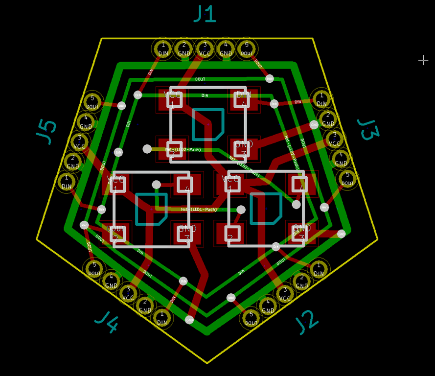
During the long hours of making four more of the PCBs – cursing my choice to use tiny pads for data connections and not doubling them – I realized that there was a far better way to do the attachment; if I allowed the boards to overlap vertically, I could use through-holes that aligned between the parts and just solder component leads into the holes. My guess is that I could do that basic board in about 1/10th the time, even less than that if I could reflow solder the LEDs. And the boards can probably be (mostly) square, which will make them easily fababble, easily broken apart, and they will fit tighter for better utilization.

Sounds like version 2 to me.

I didn’t take any pictures during this time, but it was a huge pain in the butt to get them all working; the tiny data paths were especially troublesome.

Finally that, was done, and I could turn to other matters. Four more Huzzahs were wired up:

image

and were all attached to the snowflakes.

With the Huzzah mounted close, it needed some protection, so a bit more time in TinkerCAD yielded a nice little case:

image

That’s a PrintrBot simple metal pro with a custom heated bed on it. I had the usual problem getting tolerances right, but eventually got to here:

image

Power

Whenever anybody asks me what the hardest part of these projects is, I always respond “cabling”.

LEDs are power hungry, and unfortunately small wires introduce voltage loss, which means you get color shift. If I had 3 snowflakes on one wire, the last one is going to be dimmer and the colors will likely shift as well. In my previous projects I’ve resorted to powering strips at both ends and using thick landscape lighting wire, but it’s a huge pain.

This time, I got smart.

WS2812s pull about 60 mA max if they are all white, and with 55 of them I needed 3.3 amps @ 5 volts. Since I can live without full white, I decided that 3 amps would be sufficient. And bought 5 of these:

image

One of these will be right next to each snowflake, and then I just need wires that supply something around 12 volts, and everybody will get a nice solid 5V supply and be happy. I reused the 10-gauge wire I had for the project this replaced, but I could easily get by with something like 18 gauge.

I’m not sure powering with DC is the right approach, however; it might be cheaper to go with small 5V AC power supplies and just use standard AC cords.

Waterproofing

I live in the Seattle area, and the holiday season is generally quite wet, and the electronics will need some protection from the elements.

I have quite a bit of West Systems epoxy sitting in the garage leftover from a custom subwoofer enclosure I did a while back, but their website didn’t yield much information about its conductivity. So, I built this:

image

and embedded it in a whole lot of epoxy:

image

image

Works fine…

Distractions

About this time, I had a couple of distractions. First off, this showed up from Italy:

IMG_8960

Getting it picked up, legs on it, and ordering parts to recondition it took a bit of time.

And, I had an event where I needed the snowflakes to be part of the display, so I totally finished two of the snowflakes and put them out on the house, trusting that the weather would stay unseasonably dry. Here’s the bench test:

image

You can see the DC->DC converter to the left of the lower snowflake.

I should at this point mention that pictures or video never do these colors justice; they are much more intense than they show up here.

Waterproofing part 2

To keep the attached wires in the right spots, the wires and the Huzzah needed to be supported above the PCB which will be covered in epoxy. Here’s what I ended up with:

image

After I carefully poured epoxy over all the parts of the board that needed them, the boards got hung up to cure:

image

It being about 40 degrees in the garage, they did not cure overnight and eventually I had to pull them inside to finish curing. They looked like this when they finished curing:

image

I retested them. One of them worked perfectly, the other two did not; only some of the LEDs worked.

So, out came the air rework gun to debond the epoxy in an area and then I could trace from there. I ended up replacing about 5 LEDs; from what I can tell they were touching but no soldered, and the cold weather shrunk things enough so that the epoxy could get in there. I also had one pcb trace break (really?). Then, those two got an epoxy touchup to cover over the reworked areas. .

Finally, the huzzah box got hot-glued to the back and silicone was used to plug the hole.

Not perfect, but version 1.

image

You can also see the molex connectors that bring 5V into the snowflake.

Videos:


Snowflake from Eric Gunnerson on Vimeo.


Version 2

*Lots* of ideas for version two, which might be a commercial version.

  • The whole mounting and waterproofing approach is far too finicky and may not work very well. I’m considering vacuum-forming the snowflake out of thinner plastic with both a front and back, and those can then be solvent welded (or siliconed) together to give me something that is truly waterproof. It will also give much better support for the PC boards.
  • The approach of “click-together” pc boards worked, but it required fine-tuning for each and every joint and then detailed soldering for each part. And then rework when the stresses built up. Instead of click-together, I’m going to use overlapping boards that are connected with through-hole wiring. That will take me down to 10 easy-to-solder joints per arm, or about 60 in total. I also think I can get each of the PCs to be rectangular in format, and that will make panelization easier and waste less space. I think.
  • I really need a way to reflow solder all the LEDs, and it may be time to make/buy a tiny reflow oven. Or *maybe* get somebody to do that for me, though the initial quotes I looked at are higher than I expected.
  • Moving the ESP8266 onto the snowflake board, probably on the back. That would require adding a simple 3.3V regulator for power and (probably) programming pins. I’m currently using an ESP-12; I could probably get away with a simpler one but they are pretty cheap already so it may not be worth it.
  • Add more built-in animations. Color wipes in the x/y direction, flash and off animations, concentric rotating color blends could all be done.
  • WiFi coordination between standalone snowflakes, with a dedicated network just for the snowflakes, and *maybe* a separate gateway to connect to an existing wireless network.
  • WiFi connection to an existing wireless network to allow control of the snowflakes. This might encompass setting their default set of animations, being able to download new animations, or being able to do “command control” over the wireless network, either just setting the animation that’s being run or driving every LED independently.