The Adafruit Huzzah was a nice starting point for the snowflake, but it’s both more expensive and not well-tuned for what I need. To drive the WS2812s, all I need is a single output, and I don’t need dedicated buttons on the board.
I went back and forth on whether I wanted to do two controller boards – one that used the ESP8266 and another that used a cheaper AVR, but the ESP can be had so cheaply that it hardly seemed worth it. I considered a number of different ESP modules – or even building directly from the ESP8266 and adding flash, but the ESP-12 is pretty cheap and it has FCC certification (or is claimed to, at least).
So, basically, I took the Huzzah design and looked at it in Eagle, and then pared off things that I didn’t need and did my design in KiCad. It currently lives here.
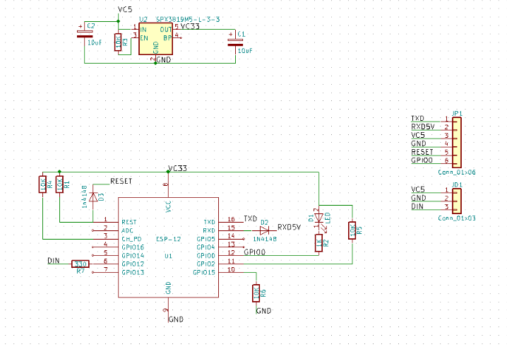
The design is pretty minimal; it has a small 3.3 volt linear regulator to power the ESP (I used the same SPX3819 as on the Huzzah), appropriate resistors to put the ESP in the right state, diodes to handle level conversion between the 5V world and the 3.3V world and two headers. There’s a 6-pin programming header that has power, serial connections, and the reset and GPI00 pins on it, and there’s a three pin header for operation that has 5V and GND in to power the board and the data line out for the WS2812 string. Simple and straightforward. There will probably be another version with another sensor; I’m going to need a way to reset these things to handle wireless setup and my new design will be fully encapsulated, so I’ll probably do something magnetic.
Here’s the schematic:
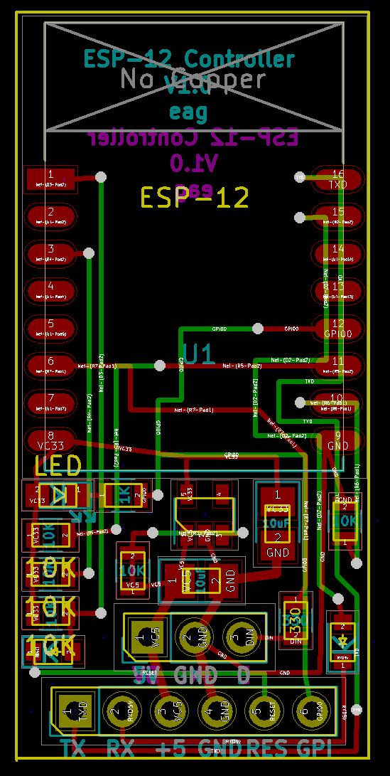
Once I had that, it was off to do the PC board layout. That is really my favorite part of the process; to go from a set of random components on the board to something functional (and perhaps even elegant) is a rewarding process. Here’s the layout.
I decided that I wanted both sets of connectors at the bottom and the ESP-12 at the top. Basically, the jacks are at the bottom, the 3.3V supply is in the middle, and the resistors, diodes, and LEDs are on the sides. All of the small components are 0805 sized, since I wanted something that I could hand-solder if necessary, and those will also reflow reasonably well if I want. Given the need for two jacks and the space they take up, there’s not a lot of margin in going smaller at this point.
One of these times, I’m going to do snapshots of what it took to get to a decent layout.
The PC boards got finished and sent out to AllPcb.com, who sent me 10 (actually, 11) copies of the board for a total of $5.49 with about a 7 day turnaround. I don’t understand the economics of how that can be profitable, but I’m not going to complain right now.
Initial guesses at the overall costs for the controller:
| Part | Price |
| ESP-12 Module | $1.78 |
| 3819 regulator | $0.06 |
| Other parts | $0.11 |
| PC board | $0.50 |
| Total | $2.45 |
No labor in there yet, but it’s just a matter of putting the parts on there and reflowing them. It should be pretty quick, and I’ll check to see what it would cost to outsource it as well.
The boards have showed up, but I was too cheap to pay for fast shipping of the other components, so they’ll trickle in and then we’ll see if my design works.


So, what do you think ?