I’m working on a project that was envisioned to use up to 32 servos, and therefore a bought a bunch of cheap servos off of AliExpress for the prototype (there may be no production-type…). They were the infamous “Tower Pro SG90 9g” servo:
Which sounded like what I wanted for my application, and they were cheap – also what I wanted – so I ordered 40 of them and waited for them to show up. Which they did in about 3 weeks, which was a bit surprising given the currently supply chain issues. While I wait, I do some coding.
I’m driving them using my Fade Animation System – one of the points of the project it to add servo support. To write that support, I read a few articles on servos and they all had an picture like this:
You can get what you want from a PWM subsystem if it’s a good one, and I’m running on the ESP32, so it’s a very good one.
It set up the PWM so that it runs at 50 Hz and 14 bits of resolution, so I get 0-16383 as my full counts. A little math tells me that 1 ms / 20 ms is 5% or 819, and 2 ms is 10%, or 1638. I code that up, look at the output on my scope, and it works as expected – I get nice 1ms and 2ms pulses at the extremes. And it works on my test servos – they nimbly go back and forth.
Along the way, I designed a little servo connector board:
The ESP32 has 16 PWM outputs so it will support 16 servos, and I had no desire to wire them together by hand.
When my big shipment of servos show up, I plug one in, write some code – in the Fade Language – and hook up a servo. My 180 degree servo works, very nicely going back and forth. For 90 degrees. I tested my code, played around with a few things, did some more extensive reading, and had my first insight.
The little 1ms – 2ms chart is just plain wrong. If you vary your pulse width from 1ms to 2ms, you will get servo movement, and it will probably be around 90 degrees, but there’s no actual standard. If you want to explore how far your servo will actually move, you will need pulses that are shorter than 1ms and longer than 2ms. How short and how long? That must be established experimentally – the counts that work on my SG90 servos are 350 and 2150 – that seems to give me full movement without a dead zone. It’s not assured that it will even be symmetrical at both ends of the scale.
I had to change the Fade servo support to allow the code to specify these two limit values. It turns out that was a good thing as there is no defined direction for servos as well; big width might mean clockwise or it might mean counter-clockwise. Neat.
That didn’t take long to figure out and the code was pretty simple to fix, but there was something else I discovered is true, at least for these servos…
180 degrees isn’t 180 degrees. The physical range of the servo is about 200 degrees, but when you drive it, 160 degrees is all that you get. Or all that I get with that specific servo, or likely this servo batch – some people say their Tower Pro SG90 servos go a full 180 degrees and others say they only go to 160 degrees the way that I do. I’m going to put that down to poor manufacturing tolerances in the electronics, but it could be that there are multiple factories assembling these things and they use slightly different parts.
There are digital servos that apparently are much better behaved. They not surprisingly cost a lot more.
There’s a nice article here that goes into most of this.
I’ve been working on a project that I think is one of my stupider ones, and it’s time to share it so that I can move onto something that is slightly less stupid.
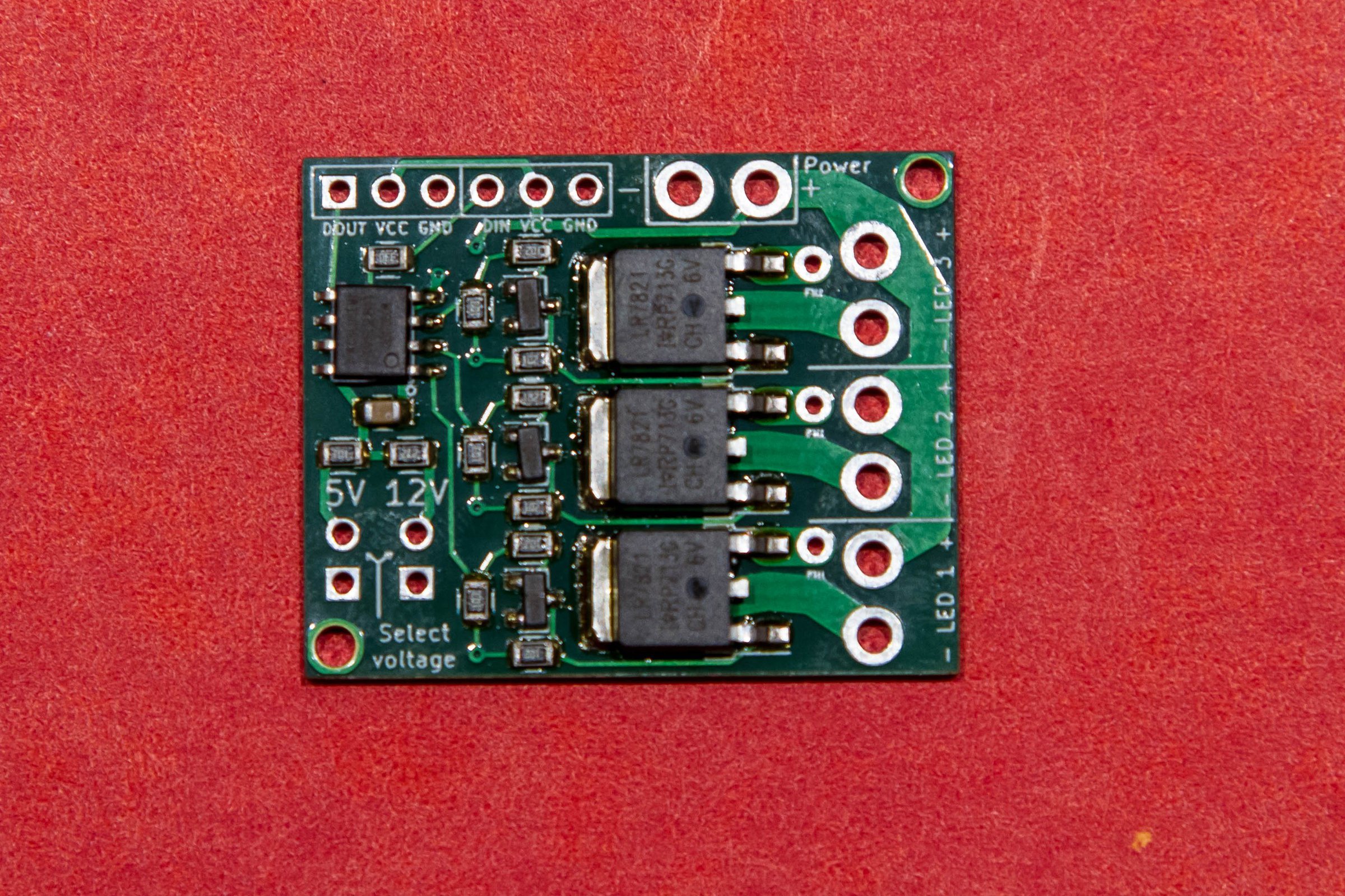
I build a little board that I sell on Tindie that allows you to use the WS2812 addressable LED protocol to drive bigger loads; so instead of having a tiny LED you could use spotlights in three colors.
It has a WS2811 IC, some transistors to act as inverters, and then three hefty power MOSFETs to handle the load. It’s a pretty hefty circuit, but to be conservative I rate the the boards at 4 amps per channel with all three channels driven – which would be 50 watts per channel if running on 12V – or 8 amps with one channel driven.
I therefore need a test circuit to validate that these are working okay, and that’s simple an ESP8266 doing some dimming across the loads.
And for the loads, I have a series of four 12V 50 watt light bulbs – these would be used in RVs before LEDs became common. They’re nice and hefty and it’s easy to see if they are working. Here’s a video that shows the text fixture and the bulbs working:
If you pay attention carefully – perhaps turn up your volume a bit – you will hear that the light bulbs are making a whining noise. That is because the WS2811 is running PWM at 2 Khz, smack-dab in the middle of the audible frequency range, and the light bulb filaments are vibrating at that frequency.
That was just a curiousity that I filed away, until I was testing a new set of boards and I had a thought:
What if I could change the frequency of the PWM?
And that little idea trigger a bunch of stupidity…
I dug into my supplies and found I had a bunch of unused ESP-32 boards leftover from when I ordered the 36-pin version instead of the 30-pin version.
I had sample code that did 16-channel PWM on the ESP-32 – the ESP-32 is almost ridiculously capable in some areas – and I ported that over to a new version, took one of my driver boards and pulled off the WS2811, wired them together, and got… nothing.
Played around some more, got more nothing. I just could not get it to work. The board would work fine when I drove it directly, but the ESP could not drive it. I also had trouble getting the LED on the board to work; it barely lit up at all. That should have been enough, but it took me an embarrassingly long time to figure out what I think is the problem…
Basically, these boards have a 3.3v regulator on it that is not up to the task. It claims to be an AMS1117, which should be a fine choice; that regulator has nice specs and can put out up to an amp of current; plenty for the ESP32. AFAICT, what it actually has is a cheap counterfeit that just barely puts out enough power for the chip to run but not to do anything useful. I could measure the outputs of the ESP and they looked fine as long as I didn’t put any load on them. I dredged a memory out of my brain that others had run into this issue, so now I’m left with a bunch of boards that don’t work, though I’m considering replacing the regulator to see if that helps.
I dug out one of my other ESP-32 boards, moved the code over, and it worked great on the first try. So don’t buy the other boards…
From concept to “music”
This section also took much longer than it should have, so I’m just going to mention the highlights…
The midicsv program is your friend if you want to convert songs into arrays of note values.
Midieditor was quite useful to simplify arrangements and fix up some of the midi notes, though the documentation is mostly absent.
Note quantization can be very useful if the midi file you download ends up with a new note starting quite a bit earlier than the note that it is replacing.
Excel is your friend when manipulating CSV files.
Midi tempo is complex. Basically, the note timing is expressed in terms of “ticks”. The header in the midi file specifies how many ticks there are per quarter note, sometimes expressed as “parts per quarter note” or PPQ. It will be something like 256 or 480.
Tempo is expressed in the number of microseconds per quarter note, and will be something like 500,000.
So, with a bit of math, you can determine:
tick time in seconds = (tempo / 1000000) * (1 / PPQ).
Then, based on the difference in ticks between when a note starts and when it ends, you can figure out the delay.
ESP-32 LEDC Fun
Conceptually, I wanted to have different PWM channels running at different frequencies. This turnout out to be far more problematic than I thought.
Call ledcAttachPin() to attach a specific GPIO pin to a specific PWM channel (the ESP-32 support here is really nice).
Call ledcSetup() to specify the PWM frequency and resolution in bits that I wanted).
Call ledWrite() to set the PWM duty cycle (either 256 to turn the light off or 64 to turn it mostly on).
And that’s what I did. And it sorta-kinda worked in some cases, didn’t work in others. I finally called ledcReadFreq() and looked at the values I was getting back. Channels 0 and 1 were always the same frequency, but channel 2 was a different frequency. Hmm…
After reading the non-arduino docs for the led control system, I came across the docs for ledc_set_freq(), which had a parameter named “timer_num”, and the description said “LEDC timer index (0-3), select from ledc_timer_t”.
Ahh… There are only 4 timers that you can use, not 16. Unfortunately, the HAL abstraction gives the impression that you can set frequency individually on each control channel. You can, it just affects other channels as well. Digging into the source, I found this table:
Ah. I’m not sure why the mapping works the way it does, but that’s the way it does, and channels 0 and 1 always use the same timer. And I think that’s a decent reason not the use the HAL, but since my code was written and I was lazy, I just mapped my channels 0, 1, 2 to 0, 2, and 4, and things were fine.
Which finally led to me declaring success, and I can therefore offer up the following videos.
Project video
Here’s a project video that shows the result. The light bulbs are terribly inefficient; with 40-50 watts of input they produce a very tiny amount of sound.
Summary
So that’s the stupid project. The software supports 3 channels but I burned out the third channel on my board when I was having issues with the crappy ESP, and since two channels is barely discernable, there’s no reason to go farther. If you would like to see the stupid code, it is here.
I’ve ordered quite a few PCB boards, but this is the first time I’ve paid for assembly as well. Documented here so that I remember the steps. Instructions here.
Do the PCB design. Duh.
Find components in the JLCPCB component catalog. Extended ones require a flat $3 fee.
Annotate the schematic components by adding a column named LCSC and putting the LCSC number in that column.
Create the BOM from Tools->Generate BOM. This will fail if you have any spaces in your filenames as the xslt processor they use has issues, but it will create a .XML file in your design directory.
Go to d:\data\electronics\bom where you will find msxsl.exe. It will work correctly. Modify a batch file to use that file and generate the output CSV file.
Edit the output file. You will need to edit it to remove parts and columns you don’t need. I imported it into excel and then saved as a .xsls file.
In the PCB editor, choose File->Fabrication outputs->Footprint position. Format = csv, units = mm, files = one file per side, footprint selection = with INSERT attribute set. This will generate a front and back file.
Edit the output file so it has the following headers: “Designator,Val,Package,Mid X,Mid Y,Rotation,Layer”
Generate gerbers as usual.
Go into the jpcpcb quote too. Upload the gerbers.
Choose “assembly”
Upload the BOM and placement files, and look at the rendering. Carefully validate the rotation of active components; there are apparently two standards. If you need to modify the placement, go edit the output from step 7 and edit the rotation column.
About 3 months ago, I wrote a post about an ESP-32 based remote control I’m building. Conceptually, what it does it allow you to press a button and hit a specific web endpoint.
Since the introduction, I wrote some code and got a prototype kindof working – the touch inputs on the ESP32 work fine, the deep sleep works okay, but I ran into a few problems.
First, the ESP32 can run on 3.0 volts but only kindof, and if you use two AAs their voltage drops pretty quickly to the point where the ESP stops working. Which means I needed a better power source, which means lithium based. I looked at primary (non-rechargeable) lithiums but they are also 3 volts (IIRC), I looked at lithium-ion, but 4.7 v is a really inconvenient voltage for ESPs; you need a regulator to get down there. Plus the 10850 cells are a bit big. Then I settled on LiFePo4 batteries, which very conveniently have a nominal voltage of 3.3 volts and are the same diameter (but shorter) than a AA, so they work well for packaging.
I bought a little battery monitoring board to protect the battery, but I’ve decided to skip it for this version. So, I think I’m set for batteries.
The second issues came up during my deep sleep testing. The ESP32 can get down to 10 uA in deep sleep, which looks great, *and* it supports “wait on touch” where it will turn on based on a touch input, which is also great. But…
The devkit boards that I have don’t support using it that way; even with the power led removed I think I was seeing about over 10mA when the ESP was in deep sleep. Not good enough. Some people have hacked their boards to remove some of the components, but traces are tiny and the board is dense, and I gave up after a few tries. I could use a module programmer like this which pulls the dev kit components onto the programmer and leaves just the raw board, but the problem there is I need a mounting solution that lets me program the same module every time.
What I really need is the dip part of the devkit board without any of the power supply or usb stuff and an adapter to hook that to the module programmer.
Since I haven’t figured that out, I went with the best deep sleep approach that I know, a rocker switch. I’m thinking that will get the power use all the way down to 0 uA.
The case
I have some plans for the version 2.0 case, but those require a fair amount of prework and new tools, and it’s nice enough that I could really use the remote *now*, so I went with with the easy approach – a laser cut box.
For touch points, I wanted some screw together pieces or screw studs, which I finally discovered were commonly known as “chicago screws”.
I wanted them in brass so that I can solder to them. The ones I got are 1/4” (6mm, actually) in length, which would be fine for my “real remote” design, but meant that I need to use 1/4” plywood for the face.
I did the design in Fusion 360. This design was not one of my better moments. I did the face in 1/4” but the sides on 1/8” so they would be thinner, but it turned out that I don’t have any 1/8” plywood left; what I have is 1/10”, so I had to redo the design. Then I measured the size of the studs very accurately with my calipers and then entered the shaft length (0.235”) instead of the shaft diameter (0.165”). And the power switch was too close to the corner so the top and side wouldn’t fit. Then I cut the top piece out of a piece of 1/8” scrap, so it was too big.
More trips back and forth than I had hoped, but it’s only computer and laser time plus a bit of wood, so it wasn’t that bad. Here’s the result:
Which is honestly pretty nice. The labels are engraved into the wood, and all it is missing is the power LED. The current plan is to glue the sides to the front and leave the back removable for access, but it’s not clear to me how that is going to work yet.
Video here:
Next up will be wiring up the front panel, assembling most of the box, and then hooking in the ESP and battery.
I’m not known for the cleanliness of my workspaces; my office desk is a mess right now, my garage workbench is a mess, as are my other workbenches.
But my electronics one is messy enough to be problematic, and the root problem is that there’s just too much stuff one the workbench; power supply, oscilloscope, toolbox, solder station, hot air rework station all take up a lot of space, and the work surface doesn’t have lot of depth, so I end up with a small clear workspace even without clutter.
A while back I was looking at my Rigol scope, and thought that I might have more room if I could mount it on the wall. And that obliquely led me to the current project.
I’ve been watching some woodworking on YouTube, and that led me to a series on french cleat walls. They are pretty popular for woodworking shops as they keep all of their tools handy. Looking at my garage space – where I do some woodworking-adjacent projects – I don’t have a lot of wall room for one of these, and most of projects I do occur elsewhere, so I wanted to keep my tools in their boxes. Not a great solution there.
But that triggered a thought about my electronics space; I don’t move my tools around and I could use the organization.
So I went looking in my garage and found that I had some leftover 12mm baltic birch plywood from another project, and I acquired some 2×3 pine for the cleats.
Making the cleat wall is pretty simple; you just cut your cleats wood at a 45 degree angle and then attach it to the plywood using a regular spacing. If you want details, here’s a video I did of the process:
I took the wall down to my workbench and attached it to the wall. Then it was time to start figuring out how to attach items to the wall; this is generally some sort of shelf or box with the mounting tabs that hook onto the cleat. First up was the oscilloscope, partly because it was big and partly because it was straightforward to design.
Oscilloscope Shelf
It’s simple enough that I could have just created a mock-up in cardboard and then used that to create the actual version, but I wanted to play a little, so I did a full CAD design. It was a pretty quick design in Fusion 360 and I’d show you a nice rendered version, but somehow it didn’t get saved along the way. Here’s what the side panel of the shelf looks like; the hole in the end is for the power cord at one end and the cooling fan at the other, and the left part hangs off the cleat:
Pro tip: The 1x stock you buy may not be exactly 3/4” thick; mine was 11/16” instead. So measure it first; for this shelf I had do sand down the back edge of the cleat.
The bottom shelf is just that, a rectangular piece of wood between the end pieces.
As a material I used some 1/4” baltic birch (probably 6mm actually), and I decided to use my Shaper Origin to make the shelf. It is held together with wood glue and some very thin wire pins shot in witn my pin nailer. Here’s the video if you want the details:
The result is nice and pretty, though I didn’t sweat trying to get things perfect; it’s not furniture:
Because of the way the cleats are designed, gravity pulls the mounting cleat both against the wall cleat and the wall plywood, and the back of the shelf presses against the second cleat. It’s surprisingly secure and yet very easy to move around.
About the time I was finishing this, I said to myself, “Self, that was fun and you made a lot of sawdust, but there’s nothing in that design that you couldn’t have done much quicker and easier with your laser cutter, so at this point I switched tools.
XBox 360 Power supply box
When I added a heated bed to my 3D printer, I bought an XBox 360 power supply to power it, and I found that they are wonderful for powering 12V loads; the ones I have provide up to 16 amps of power. So I bought a second one from Goodwill for $4.95 and have used it when I need a hefty supply for testing (like my WS2811 expander which I stress test with 3 50-watt 12v light bulbs). Cheap, compact, and lots of cheap power – what’s not to like.
Well, I don’t like that it’s cluttering up my workbench, so I’m going to build a box for it.
Here’s the CAD design, the laser-cut parts, and the final result. It’s cut out of 0.10” (2.5mm?) plywood that is strong and easy to cut on the laser (mine’s a GlowForge) and then glued together with wood glue.
I measured the power supply with my calipers and it ended up just on the tight side; the power supply slides in but barely. The big cutout for the close end is because there are air holes there.
The other end of the cable currently just has a set of speaker terminals that accept banana plugs and the enable wires soldered together so it’s always on. Sometimes in the future, that cables going to terminate in a power-supply box with an on off switch.
The xbox power supply hangs up high. And now I need a place to plug it in as the cord isn’t long enough to reach to the outlet under the workbench.
Power strip box
Another simple box, with the dimensions defined by the size of the power strip that I wanted to use. The design is quite simple with a bit of an assembly caveat; the box has both a top and a bottom so you have to assemble it around the power strip.
Resistor decade box
I built the decade box a few years ago based on this instructable. I do a fair bit of work with LEDs and I often find myself wanting to pick an LED value based either on measured current or brightness. I used to do that with a potentiometer, but it’s much easier to use a decade box.
The design here just has two end hangers; one end is attached using the output posts for the decade box, and the other one is just hot-glued on.
You might notice there are some smoke marks on the wood; if I wanted nice I would have masked them off but that was more work than I wanted for this.
Wire hanger
Just one more design for the first wave; I knew I would have wires running across the board and wanted a way to support them:
A simple three-piece design hold up a power cord. It’s tilted because of the weight of the cord is heavier on one side; I’ll probably do a version with a single hanger in the middle. Or I might cut some one-piece hangers out of 1/4” plywood.
Video tour
If you would prefer a video tour of the completed items, you can find it here:
Power supply hanger
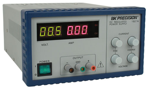
When looking at some of the small Chinese power supplies that are out there, I got a line on a nice surplus BK Precision 1627A on Ebay for $55 and ended up buying that instead. I have an older 4 voltage power supply (+12V, –12V, 5V, and adjustable) that I’ve used quite a bit, but it’s pretty rare that I need multiple voltages these days, I already have the hefty 12V, and I’m going to be adding some dedicated 5V supplies as well. I haven’t used +/- power supplies in a long time, so I think the old supply is going to get packed away for now.
To do a hanger for this looked a bit more challenging than my previous hangers because this is bigger and it weighs 16 pounds. I did the design and cut it out of 1/4” plywood:
The frames here are about 10” x 7” in size. They are cut out of 1/4” (probably 6mm, actually) and glued together.
Pro tip: Go back and look at the picture of the power supply picture above. If you look closely on the side and the talk, you will see some screws sticking out. If you measure precisely and cut to that precise measurement, the pretty holder you create will *not* fit over those screws, and you’ll need to remove the screws – and maybe the equipment feet – to get the frames to fit over the item (the power supply in this case).
Not only did I do that, but the first time I put the hanger on I had it on the wrong side, so I had to repeat it. But I did get to the final result:
Futures
One of my goals was to get my Fluke multimeter off my desk and up in the air, but there are some issues, the biggest one being that the digits are in shadow if the meter is vertical against the wall. I’ve had some designs that put it at the same angle the stand in the base does, some designs that let you modify the angle, and another idea that I might just add some white LEDs to the side so it could be vertical.
There will be a power supply station close at hand; I think it’s going to support 12V from the xbox supply, 5V both on banana plugs and on multiple USB plugs, and I might integrate one of the cheap chinese boost/buck supplies to give options.
Finally, there’s the right side of the bench, which has my soldering iron base and my cheap chinese hot-air rework station. I may end up with a cleat wall on that side I can get them up as well.
A couple of years ago I did an ESP-32 based controller for our landscape lights and fountain. It has a nice web-based interface, if you like the way interfaces looked when HTML was young…
In addition to this web page, you can hit http endpoints directly, so you can control things with either a browser or an HTTP app on your phone. It’s a bit of a pain to dig your phone out and run an app to turn on lights, so I’ve always planned on doing a handheld controller. It’s going to be pretty simple; just a set of buttons and an app that sends requests to the actual controller.
At least, that’s how it started…
My original plan was to use an ESP8266 because it’s smaller and to use some normal momentary pushbuttons:
That would have been fully functional, but I didn’t really like the way the buttons looked and I didn’t like the low-power options very much. I was looking through the ESP-32 technical manual and remembered that the ESP-32 has a touch-sensor subsystem that supports 10 separate inputs. That means I can do a cleaner-looking controller that has metal touch points rather than buttons, and the ESP supports wake on touch, so I can put the controller into deep sleep.
Conceptual design
Here’s a very quick drawing:
Here’s what I’m thinking for the design. There are 5 circuits to control:
Fountain pump
Bed lights
House lights
Umbrella lights (strips under umbrella)
All lights
In addition, I want to be able to control the brightness of the umbrella lights in 5 steps; 20%, 40%, 60%, 80%, and 100%
Coincidentally that requires 10 different controls, which is exactly how many touch inputs the ESP has, so that worked out well.
The controller will be remote-control-shaped, with batteries (tentatively 2 AA alkalines) near the bottom, the ESP in the middle, and an array of touch points at the top.
Sleep battery calculations
There is an assertion that the ESP32 in deep sleep only pulls 2.5uA. A typical alkaline AA cell has a capacity of about 2000-3000 mAH, so if we do some math:
Hours = 2000 mAH * 1000 (convert to uAH) / 2.5 = 800,000 H, or 33,000 days. If we could really get that, that would be 91 years on standby.
Let’s do the calculation the other way; if we wanted batteries to last a year, that would give us:
2000 mAH / 365 = 5mAH per day, or 228 uA of constant current. If I can hit something under that, I’ll get a year out of the batteries.
Getting that to work is going to require me to either modify the ESP-32 devkit boards I’m using or switch over to a raw module and separate programmer, but that’s a matter for another post/video
My skiing penguins project has been up and animating for a few weeks, and I thought I’d write down the process for others so that they can learn from what I did. And also so I can remember what I did and why. There are some other blog posts that talk about some of the specifics for the sequence controller I built.
First off, there’s a video here that shows the final result.
The my initial idea was to do something with LEDs and single frame animation; see some of the animations that were done at ZooLights at Pt. Defiance many years ago was what got me into this hobby. I had a big garage roof that was unutilized, and after some discussion with my wife we decided that skiing penguins was a good place to start.
CAD
I started looking around for online penguin designs to use as a starting point and found a couple. Then I started up Fusion 360 and created a new project.
I design (and sell) LED ornament kits, so I’m used to doing these designs. Here’s a video that shows the technique that I use to space the LEDs out evenly along an outline; that is what I used for all of the penguins. Here’s a in-process look at one of the designs:
and a final one:
The final designs were too big to cut in my laser cutter (glowforge), so I had to break them into two pieces. The puzzle-piece line gives me two individual pieces to cut that can easily be put together again.
The animation has 15 frames, which meant 29 individual pieces to cut.
Cutting
I figured out what sizes of plexiglass I needed and bought the plexiglass from my local TAP plastics; it was about $90 worth. I didn’t want to spend a lot of time splitting pieces on my table saw, so I defeated the door interlock on my Glowforge for the larger pieces:
You really shouldn’t do this if you don’t have laser safety glasses designed for your particular laser’s frequency. In this case, I wore my normal safety glasses and closed off as much of the opening as possible; I now have a nice set of dedicated laser safety glasses. Don’t do this unless you understand the risks.
Here’s all the cut pieces stacked up:
This is a penguin prototype:
This was actually constructed earlier; it was used to determine size, and we decided to go about 25% larger. Thankfully, Fusion made this fairly easy to do.
Here’s the first production frame:
You can see the glue residue along the joining line. At the left and right sides there are short connectors that overlap the joint and provide much needed stiffening; they are on both sides. The squares with holes are spacers; the penguins will mount to wood supports and the spacers hold the wood away from the wiring that will be on the back. Zoom in to see the fine details.
Here’s the pile of penguins all glued together and ready for LEDs.
First light on the first frame:
Green was planned for the body outline rather than the white in the prototype but I didn’t have enough green LEDs at the time. The LEDs are brightness matched to look similar to human eyesight though the blues look too bright to the camera. Only 13 more to go!
Here’s what the penguin looks like with the leds off:
Sorry about the messy and distracting background. For each section of LEDs, there are two sets of bare copper; one that is connected to 12V and one that is connected to ground. Leds are grouped based on their voltages; green and blue run in groups of 2 while reds run in groups of 4. At this point I realized that my ski poles had 9 leds which means that I had two groups of 4 and one individual LED, which was a pain. Each group has the appropriate resistor to set brightness. There are 70-odd LEDs in this frame, so figure something near to 200 solder joints.
Here’s a picture of the workbench mess:
That’s not that bad except there is more mess here:
and here:
To waterproof all the wiring, I took the penguins outside and hit them very heavily with clear acrylic spray. I’ll know how well that worked when I take them down:
Here’s a view of them drying. They have waterproof power connectors attached and have frame numbers marked on them.
And then they were each mounted on short pieces of 2×3 wood which would have been painted if I had time; maybe I’ll do that when I pull them down after they have dried out. You can see the wiring quite well in this shot, and we can see that it’s frame “J”, or the 10th frame.
The next step was to build the wiring harness. I did a diagram of the expected layout in Visio:
From that, I went out into my driveway, took a couple of tape measures, and laid out what I needed. The controller was planned to be under the roof where “K” is, so I would run wire to that point and then leave an extra 10’. I unfortunately don’t have any pictures of this process; I was racing the weather.
Basically, I would start at “A” in the diagram, leave a couple of feet of slack cable, run it up to D, across the top, and then down to K and leave 10’ at that end. Each cable gets an adhesive label with the circuit letter at each end, and those will later be covered with clear packing tape to waterproof them. Continue the process with each cable all the way through K. The cable is 22-gauge alarm cable; I have used twinlead in the past and I have to say that this cable was a huge upgrade in terms of ease of use, and at $31 for 500’ is was pretty cheap. I did calculations on the voltage drop and decided that it wasn’t too bad (about 7% IIRC).
Once I had all the cables, they got bunded together with wire ties at every branching location and then additional wire ties to make the harness easy to handle. I got it all done just as the rain came down for real, and headed inside. Each penguin location got the other half of the waterproof connector soldered on and then covered in heatshrink tubuing, and the controller ends got stripped to be connected to the controller. Here’s the final roof harness:
The penguins got installed on the roof with various arrangements of wood to support them and were plugged into the harness. I then spent a day or two figuring out how to do the penguins in front of the house; they are supported on 1/2” metal EMT tubing. I also created a separate harness for those penguins (one in the air, one crashed in the tree, and then a small one where the one in the tree lost his poles and skis) using the same process.
I finished building the controller:
Nearest to us is the ESP32 controller board that runs the animation software, and behind it are two custom 8-channel MOSFET switching boards. Attached to the back MOSFET board is a series of LEDs used for debugging.
The ESP runs custom software that drives the ESP32’s 16-channel PWM hardware. The ESP32 is ridiculously full-featured for the price. One of my goals for the project was to *not* have to pull the controllers out of their installed location to update the animation, so I created a really rudimentary web-based IDE and an animation language:
This is the current active view from the ESP running the penguins as I sit here and write. The left textbox shows the code and the right one shows errors if there are any. I wrote the animation outline and programmed it in, and then took my laptop to the garage and we’d watch the animation and I’d tweak it as necessary, it took us about 10 minutes to get what we wanted, and I would have spent more than that on a single iteration of “unplug the controller, take it downstairs, plug it in, modify the software, compile it, upload a new version, take it outside, plug it back in, and see if it worked”. That worked very well.
I’m calling the language “Dim”, because it’s good at dimming things and not very smart. In the code “DI” means drive a specific channel to a specific brightness over a specific cycle count (each cycle is about 10mS, so it runs at 100 Hz), and D lets you specify more than one operation to occur at once during the following “A” (animate) command. The language does have for loops but is desperately in need of functions/methods for this usage; I have those in a newer version.
Here’s a bit of code running on a second instance of the controller that flashes 5 of the ornaments I make in a random pattern:
Finally, here’s a daytime tour of the installation which shows the penguins mounted on the roof and in front of the garage and the controller board with terminal strips.
I’ve been working on a little ESP32 expansion board/shield for an LED project I’ve been working on. One of the nice things about the ESP32 is that it has a peripheral known as “LED control” that provides 16 independent channels of PWM for controlling LED brightness, and my project uses that capability.
One of my projects is going to require all 16 channels, so I wanted to do a board that would support 16 channels, but I also wanted a version of the board that would only support 8 channels. I started with the 8 channel board and figured out a way to build a single board that would support 8 channels and also function as an expansion board to add the other 8 channels. I thought the approach was interesting enough to share it here…
Let’s start with a picture of the board:
I’m using the 20-pin development board, and it turns out that of the 16 channels supported by the LED control peripheral, half of them are on each set of pins. I started doing an 8-channel version of the controller; you can see the primary pins on the right side of the board that come into the center of the board and then head down into the MOSFET region of the board. That design was fairly simple to do.
Then I needed a way to do something with the 8 channels on the other set of pins. At that point, I realized that if I could use the same board to get the other 8 channels if I flipped the board over:
On the primary board, the pins for channels 9-16 on the left side of the board are connected to a header. The ESP32 will be connected to headers on the top side of the primary board, and then we will add a header to the primary board expansion pins – pins 9-16 – on the underside of the primary board.
We will then take a second board and flip it upside down. That puts the header pins that are connected to the MOSFETs on the left side of layout directly under the header on the primary board connected to the expansion pins, so we can just put a complementary header on the expansion board and just stack them together.
Here’s what it looks like in the real world. This is the primary board with headers for the ESP-32 on the left and MOSFETs on the right. That is set up for 8-channel mode.
To enable 16-channel mode, we flip this board over and add some headers. The top header connects to pins 9-16 from the ESP32, and then there’s a single pin on the bottom which connects to ground (if I do a future version I’ll add an extra pin on the left) to provide a bit more support.
We then take a second board and set it up as an expansion board by adding the complementary headers to it.
We can then finally stack the expansion board on the back of the primary board and add the ESP32:
That gives us 16 outputs.
Here’s a short video demo of the controller:
And a second video that show my first project using it:
JLCPCB did a nice job, and the boards look fine. Except:
Yeah. Those pins are beautifully aligned a very precise 0.1” from where they are supposed to be…
Pro tip: Print out your design and put your components on it so that you can check the design.
Meta pro tip: Follow your pro tips.
Anyway, that’s not the only problem; it turns out that the power and LED parts of the connector are right underneath the end of the board, so you can’t use a normal header on them (you could use a right-angle one if you wanted), so I did a new revision of the board with 1.0” rather than 1.1” for the ESP and extended the board so the connectors are out on the end. That’s on the slow ship from China right now.
Then I did a bit of bodging with some long-tail female headers so I could still do testing.
Then I put a header for the LEDs and carefully soldered 8 resistors and LEDs to the output pins, so that I have an 8-channel version available for writing software.
The MOSFETs are pretty darn small, but soldering them was mostly okay. I didn’t bother doing a stencil for this rev so I could reflow, but I will likely do that for the next version.
I have not yet tested what I think is the coolest part of the design; the board is both a main board and an expander board; you can connected a second version of the board on the back of the one with the ESP32 connected to it, and it will get you channels 9-16.
It’s doing a “breathe” on all 8 LEDs with varying timespans for the delay action.
This is the 6th or 7th time that I’ve written sequencing software; there was a Motorola HC11 version, two AVR versions with AC dimming, a 4-channel chaser, and a couple of WS2812 versions.
They were all very simple; take the current state of all the output and drive the outputs to a new state over a given period of time. That works fine, but writing the animation can be annoying and it’s not very compact. This time I wanted to do something different and more elegant:
Here’s my spec:
That means ‘loop variable %A from 0 to 7’, and then execute a 100 cycle (1 second) dim of channel %A from its current state to 1.0 (full bright), and then do the same dim back down to zero.
I also wanted to write the vast majority of the code on my desktop, so I took a break and wrote three blog posts about how I do that. It’s basically compile-time dependency replacement with unit tests mostly written using TDD.
Then it was off to writing a *lot* of test code and a lot of classes; 18 difference source files, only two of which are ESP specific at this point. And 15 test classes to drive the tests. It mostly worked great, I did 95% of my coding and only had once latent bug that I had to track down on the ESP32. It was weird one that turned out to have very random behavior. I suspected it was uninitialized data, and that turned out to be mostly right; two subsequent calls to a method used the same stack and I forgot that strncpy doesn’t copy a null. But it all works now. Here’s the code the video is running:
Variable %B is used to change the cycle count for the operations from 100 to 10 in steps of 10, and then the inner loop cycles through the 8 different outputs. Everything works great.
The code all lives here if you want to see the actual code or a more realistic testing example.
Next steps:
Wireless implementation to do the connection to the ESP
Save and load of the animation
Web interface to edit the animation.
Change the language to move the cycle count into the “dim” command, as it’s not necessary for the loop commands.