Monthly Archives: November 2017

Snowflake update…

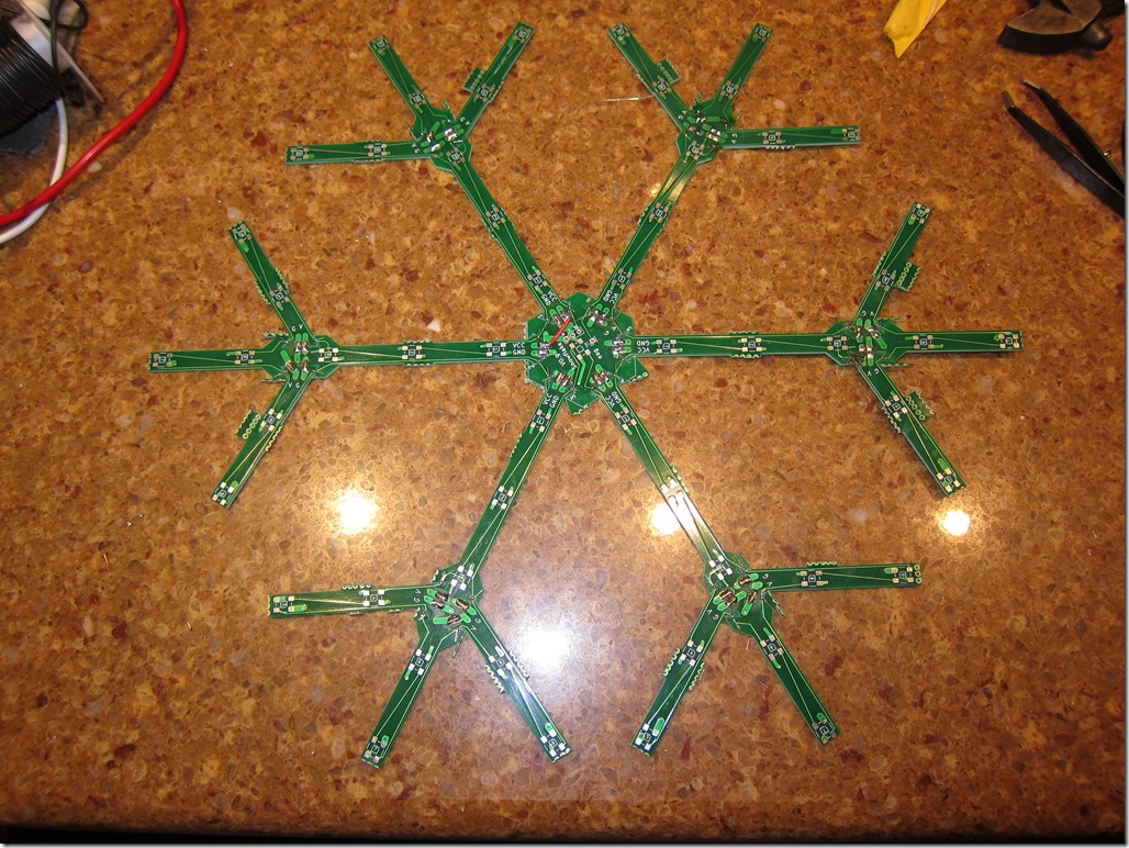
Have made decent progress on the snowflake. I have two PCBs assembled and populated. The right way to do it would be to use a reflow oven, but I’ve settled on using my new hot air rework station and solder paste to do the data lines – since the pads that I need to connect are tiny – and hand soldering everything else, including the LEDs. I did reflow on a test LED and it worked, but I had to get things hotter than I would like.

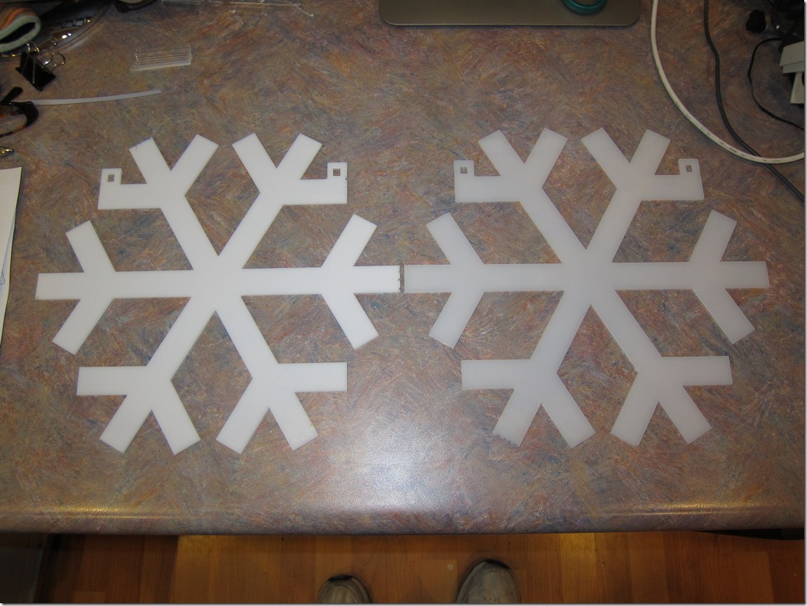
I finished the outline design and cut the snowflake fronts from white acrylic. This was a bit frustrating; the Glowforge is advertised as being able to cut about 11.5″ in the forward/back direction, but they haven’t been able to achieve that, so I had to cut slightly smaller than I wanted.

I used one sheet each of #7328 and #2447 acrylic so I could see which one I liked better:

IMG_8876

After playing around a bunch (something like 15 variants) with both plastics and with keeping them different distances from the LEDs, we settled on 2447 spaced about 10mm away.

Then it was off to Tinkercad to design a clip that would hold the front to the pc boards, which finally led to this. You can see the clips (printed in clear PLA) holding the snowflake at the right distance.

MVI_8888 from Eric Gunnerson on Vimeo.

After a false start or two, I think I have a handle on how I want to structure the animation code; it’s nice and mathy…

Now I just need to order some more Huzzahs to drive the other snowflakes, figure out how I’m going to handle the cabling, and buy some waterproof 12V –> 5V buck converters (I’m tired of worrying about voltage drop).

The video is powering the LEDs from a USB port using tiny wires, and the 5V supply is sagging down to around 4 volts because of the load. So, it will be brighter than this.

Snowflake PCBs…

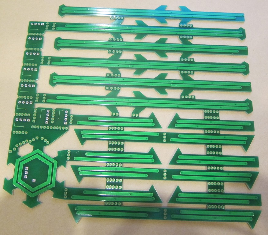
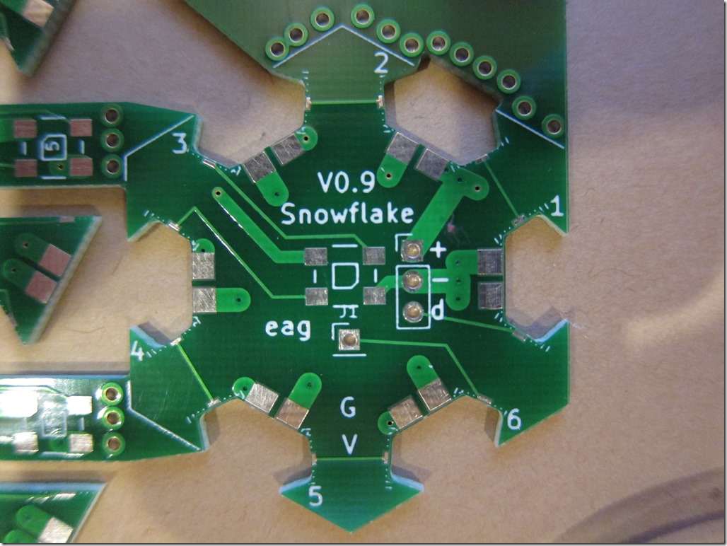
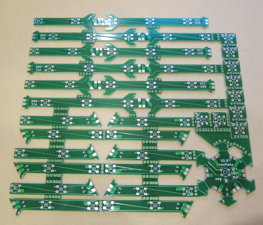
The PCBs showed up very quickly. Here are front and back pictures of them.

IMG_8864

IMG_8865

IMG_8869

They look pretty nice and have holes in all the right places. Because of the design, I need to cut them apart by hand.

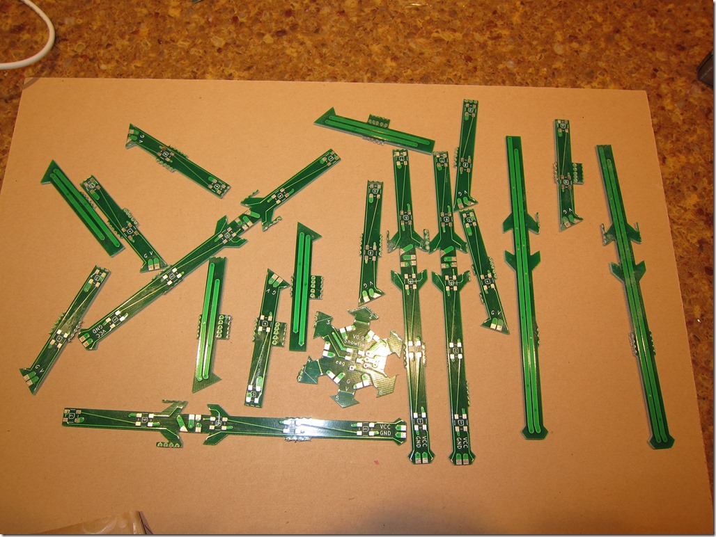
I used my Dremel osciallating multi-tool, but frankly I think the normal Dremel would be a better choice.

That gave me a pile of parts:

IMG_8871

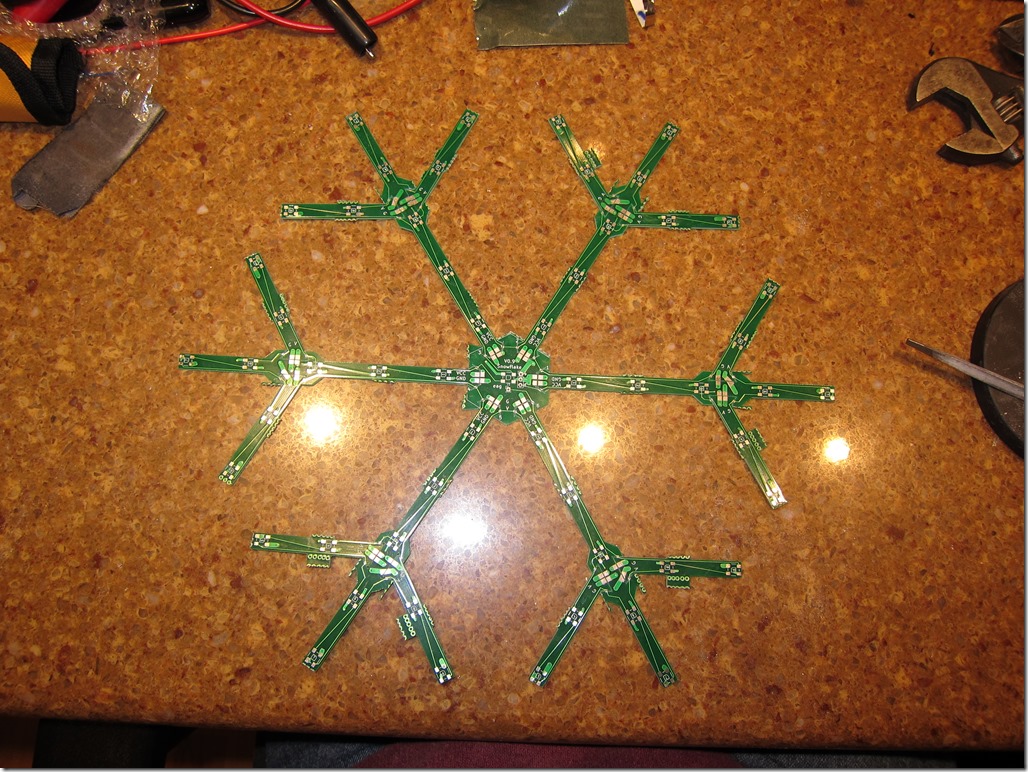
Next, it was time to assemble the pieces. If everything was exactly sized, all the parts should have fit together perfectly. As it was, I had a few protrusions to file down and then I needed to file most of the pieces to get them to fit together. Took about half an hour.

And then, the first view of the snowflake board assembled.

IMG_8872

The *plan* was that there would be copper right to the edges of the boards, and then they could just be soldered together.

What the fab *did* was pull the copper back from the edge by a little bit, so there was a gap between each of the pads that I needed to solder together. The power and ground pads are pretty big, and I could easily bridge them with a bit of bare copper wire.

The signal lines were another matter. The pads are much smaller, and with the copper lost by the fab, I just had a hairline of pad to solder to. I ended up using very fine wires to bridge the gap, putting the super-fine tip on my Hakko, and very carefully soldering the wires on. It was pretty exacting work, but it got easier over time.

IMG_8873

The design was perfect except for a missing via that leaves a broken connection to the Vcc line. I fixed it with a short bit of red insulated wire.

I ordered a new hot air rework station so that I can reflow the WS2812 LEDs onto the PCBs, and I’m going to use that to solder all the little jumper wires that way.

While I wait for the new tools to show up, I’m going to write some code.