Browsing posts in: House

Countertop CAD CAM

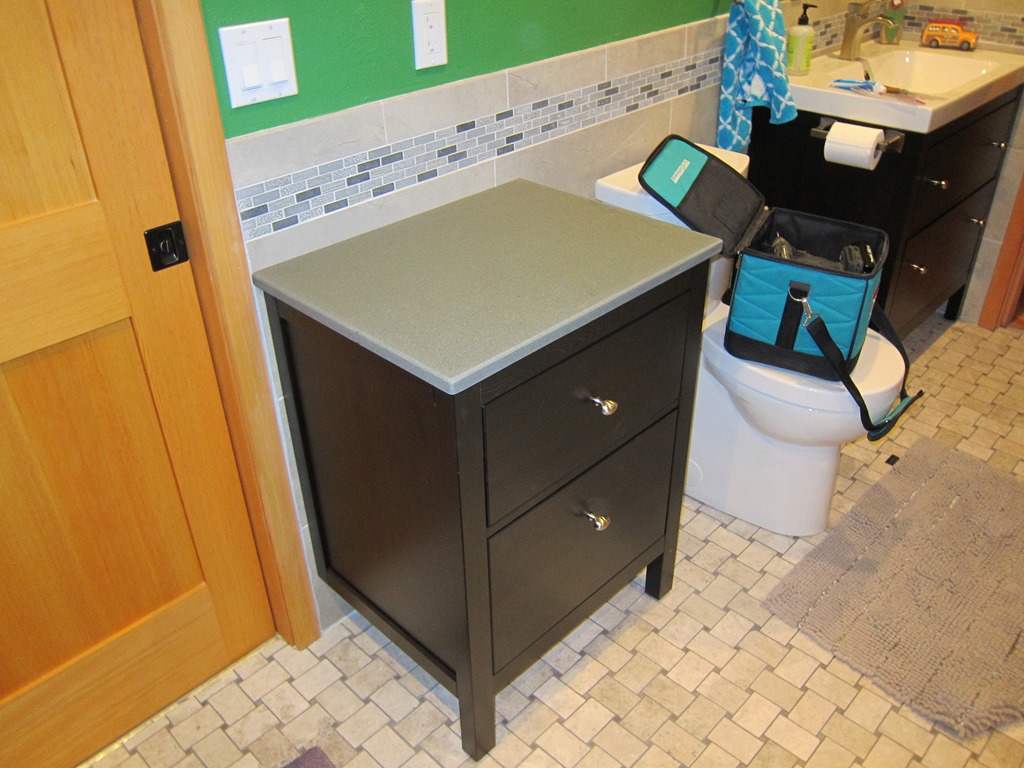
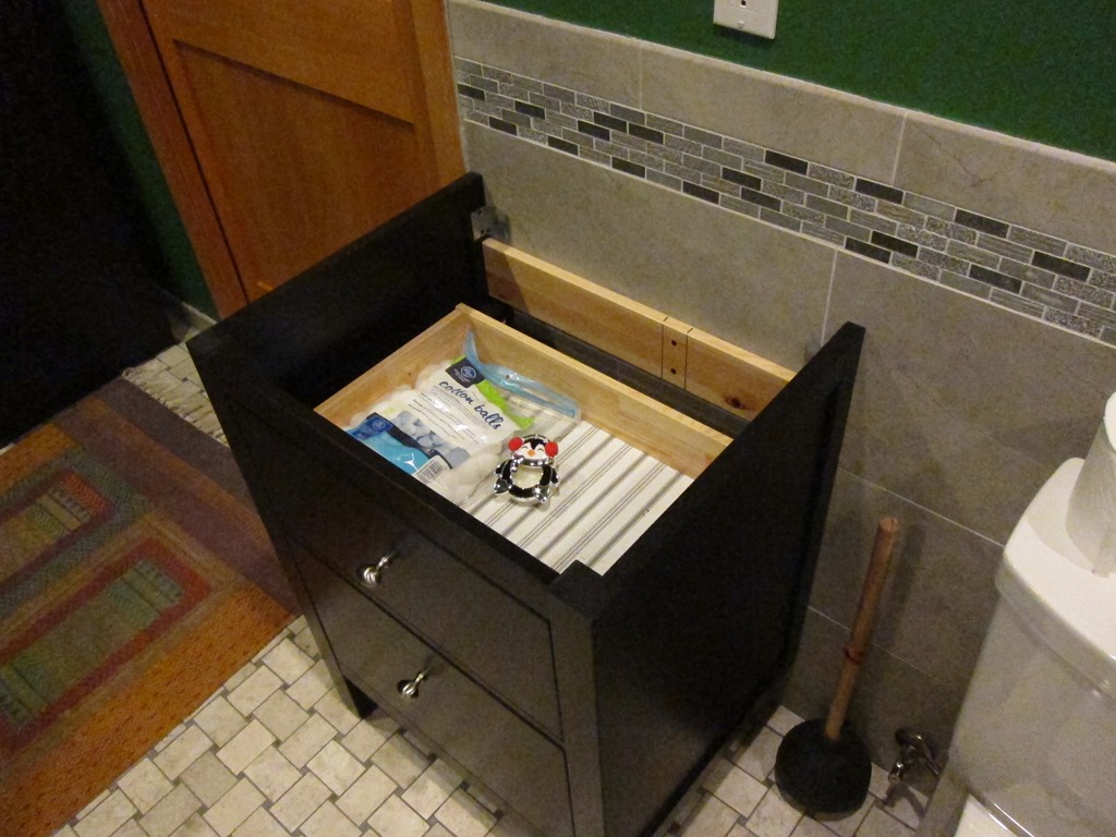
One of the leftover tasks from a bathroom remodel is to put a countertop on one of the small storage cabinets:

IMG_9414

We originally were going to have somebody fab a piece for us, but it’s a small job and they never really got back to us. So, it sat like this for a *long* time, but now it’s time to get moving on it.

After considering marble, we settled on doing solid surface because I can fabricate it with the tools that I already own. A little research took us to solidsurface.com, where we found a nice leftover piece of countertop in a color known as “Oregano Sand”, which we hope will go well with the overall color palette. That won out over white because we already have a white toilet and sink. A 20” x 43” x 0.5” piece was $116.33, and since I’m going to do a built-up edge – so it’s a full 1” thick on the visible part – I also picked up a tube of adhesive that is mostly color matched to the color of the material.

The fabrication approach I had planned was pretty simple:

  1. Carefully measure the size of the base and add 5/8” on the sides and front.
  2. Cut the solid surface piece on the table saw to the exact dimensions needed
  3. Round the left and right corners.
  4. Notch the left-back part to fit around the door trim
  5. Glue on other pieces underneath the top with them sticking out a bit.
  6. Trim the new pieces with a router and a bearing string-cutting bit so everything matches
  7. Round over the top edge with a rounding over bit.

The downside of this is that I’ll need to be doing some cutting on the table saw, and that’s not my most accurate tool, and I’ll likely need to do some sanding to clean things up.

I was also going to say that notching out the corner for the trim would be a big pain, but I just now realized that the cabinet is only held in place by two screws into a stud, and it would be absolutely trivial to slide the thing over to the right by 5/16” and eliminate the notch.

But anyway, I don’t like doing the big things on the table saw.

And then I realized that I could easily just do a CAD design for the countertop and cut it out on my shaper origin. That will give me very good tolerances and there’s no reason to expect that it won’t require less rework than the table saw, and there’s much less chance I’ll slip and do something bad.

So, I went of and did some Fusioning, and came up with the following:

image

A simple base that is the side of the cabinet, and then a counter on top with nice 1/4” rounded corners on the front and a little notch at the back. I’ll be getting rid of the notch since I decided to just move the cabinet over slightly.

I’m currently missing the pieces that will be between the countertop and the cabinet to make the edge thicker. I’m going to model them on top of the countertop as that will be simpler to do. It ends up looking like this:

image

Note that there are three built-up pieces, each 3” x 19.25”. That allows them to overhang the front by 1/8” and overhang the sides by 3/16”.

Fabrication

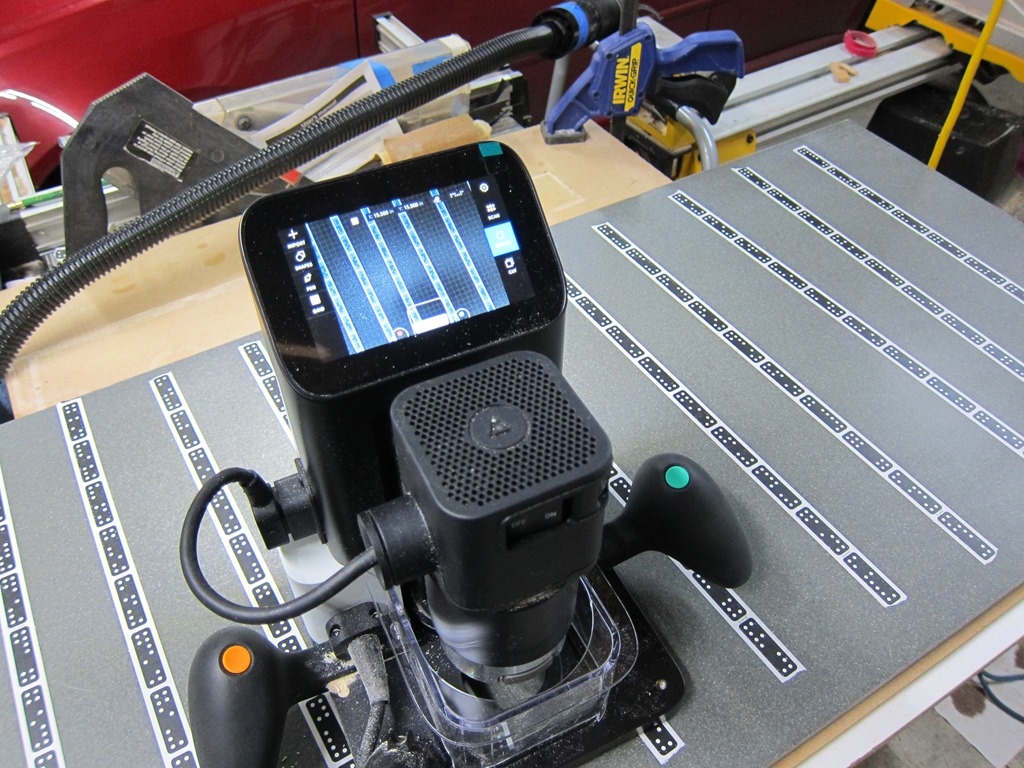
I decided to use the shaper origin to do the fabrication:

IMG_9418

That solid surface stuff is *hard*, it’s a bit like working in hardwood. I ended up only cutting 3mm at a time.

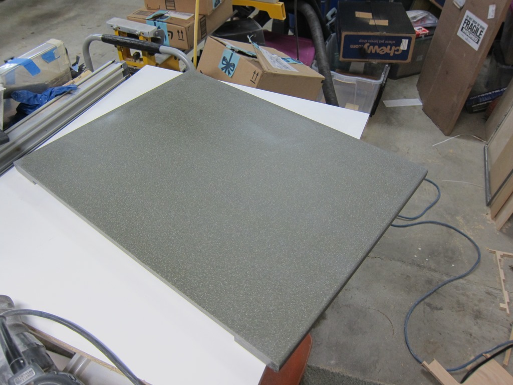
In retrospect, the shaper wasn’t the best choice for this; the size was fine but the edges weren’t as smooth as I had hoped. But they were close enough.

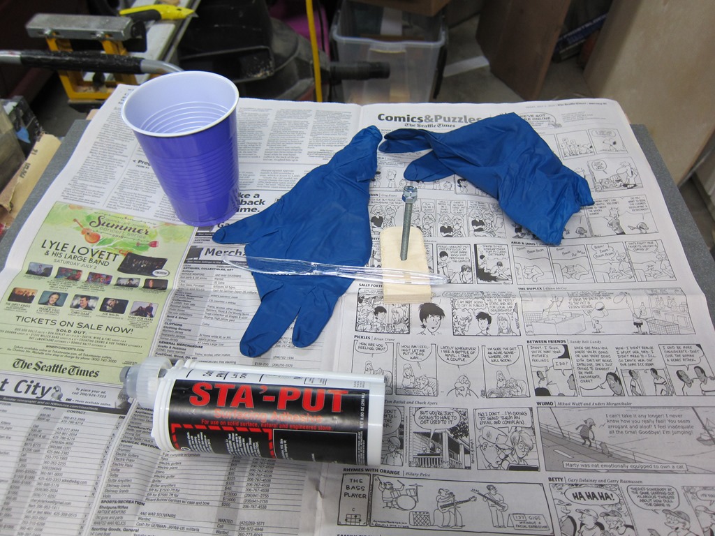
To do the layup, I needed the following items:

IMG_9423

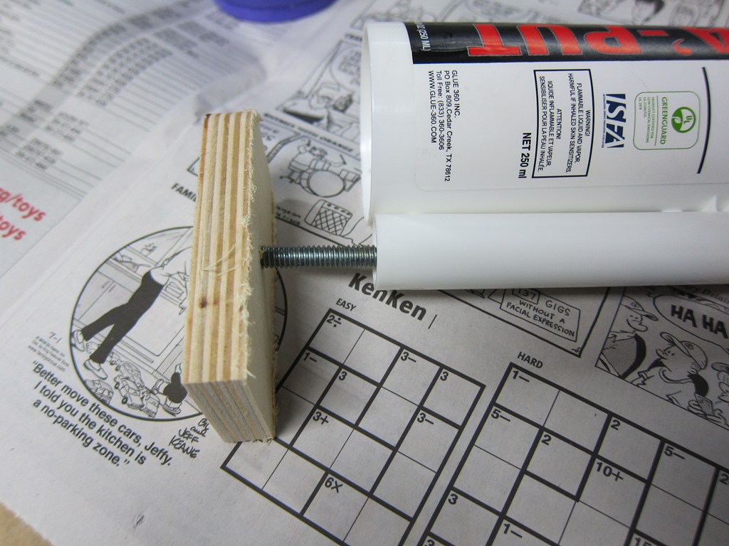
The glue is a two-part color matched adhesive. And that presented a problem; the glue is in two parts, and they need to be dispensed in equal ratios. Real installers have nice guns (like caulking guns) that dispense both at the same time and run them through special mixing nozzles, but I didn’t want to buy a gun just for one use.

So, I built that little bolt thing that the knife is sitting on. I’ll open the tube and then use it to press the piston in the correct amount on each of the tubes, and then mix it together. Here’s what it looks like in use:

IMG_9425

This worked really, really well; both liquids are fairly fluid so it pressed out easily.

A large amount of color-matched (mostly) adhesive, a tiny bit of hardener:

IMG_9426

This stuff is really, really smelly; tons of volatiles; you want good ventilation and/or a good chemical mask. After a good mixing, I started spreading it onto the build-up pieces and putting them onto the big piece. This worked fairly well except that they want to slide sideways.

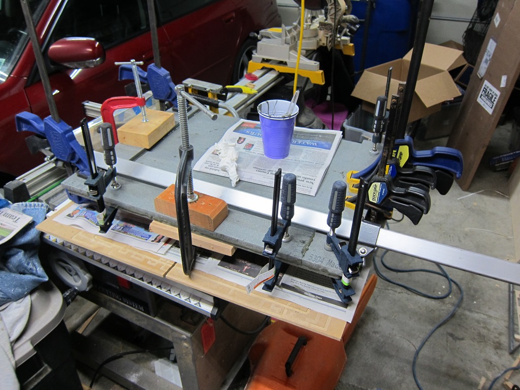
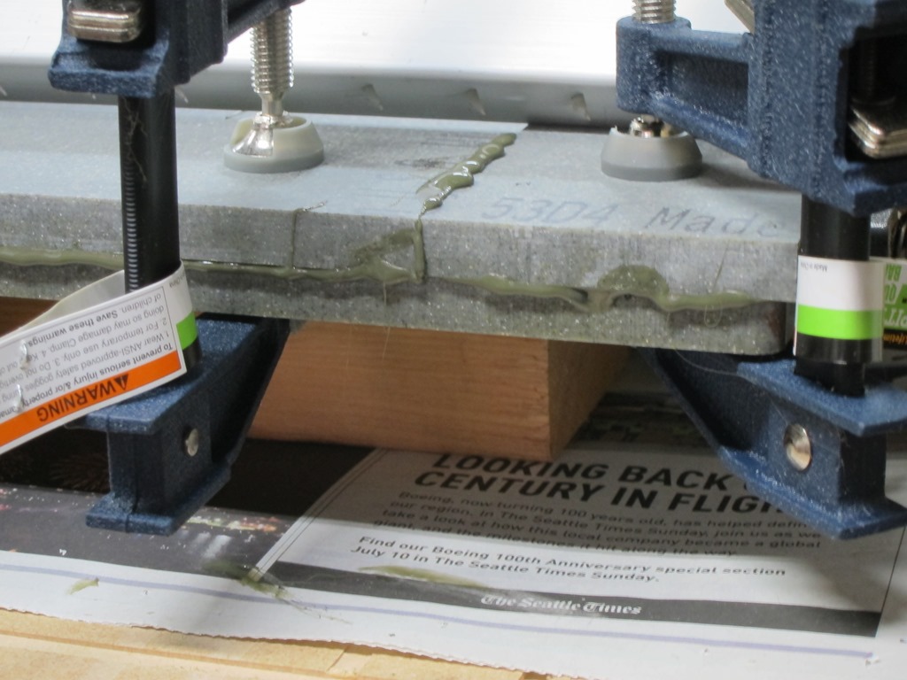
And then it was time for lots of clamps:

IMG_9427

Closeup:

IMG_9429

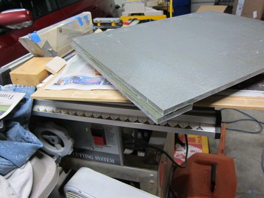
Here’s the worst edge. Yes, it’s not parallel, no it’s not a problem:

IMG_9430 

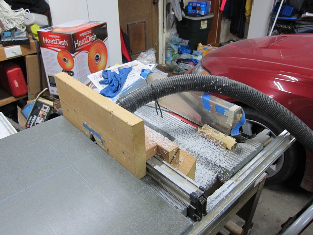
The buildup parts are trimmed to be the same as the big piece using a router and a bearing bit. This went quite well, and produced a lot of chips that were like the fake snow you see at Christmas.

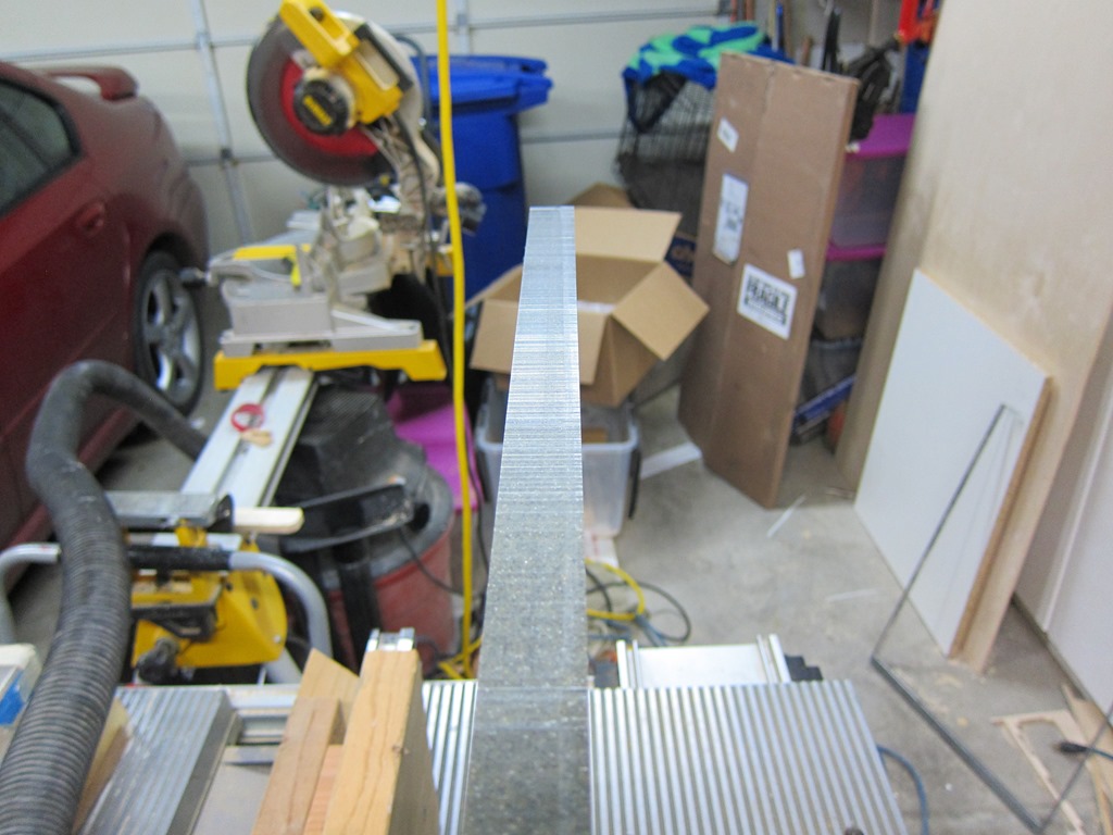
Here’s a long edge. Wavy wavy wavy; that’s from the shaper not tracking perfectly. Nothing that a ridiculous amount of sanding won’t fix. I stuck with the random orbit because I didn’t want to risk worse gouges with the belt sander:

IMG_9435

Once all the sides were square, the edge was rounded over with a 1/4” roundover bit with a bearing:

IMG_9438

Then sanding, sanding, sanding to get rid of the ridges and sand out the scratches from the router table. Worked my way through grits, 80/100/150/220/320. Here it is mostly cleaned off:

IMG_9440

and installed on top of the vanity with clear silicone adhesive. The color looks quite nice against the accent tile.

IMG_9441


Clopay Pinchproof door hinge #1

When we first bought our house nearly 20 years ago, one of the first things we did was to replace a 20-year-old wood garage door with a nice sectional from Clopay.

This door used a proprietary design known as a “pinchless” design; rather than using a simple  hinge that attaches to the two parts of the door, they designed a hinge where the top part is attached to top door upper door panel, and then there are little arms that are attached to the lower panel with a steel pin. Each hinge is slightly different.

Over the years I’ve had a few hinges break; it’s really common for one arm of the hinge to come off of the little pin, which puts more pressure on the other side. Over time, that side will break, and the door will start working poorly, and the failure may cascade to other hinges.

I broke 3 or 4 hinges, and whenever that happened, bought a new hinge and replaced it.

Last month I found that another hinge had broken, searched online, and found out that Clopay has not only discontinued that design, they have stopped making replacement parts and. You can find some of the hinges available, but not the #1 hinge that I wanted.

I tried a jury-rig that rapidly failed, thought about a new door ($1000, no thanks), and then decided to fabricate one myself. My goal is to beef it up with slightly thicker sheet metal and make the arms that keep breaking wider.

Reverse engineering

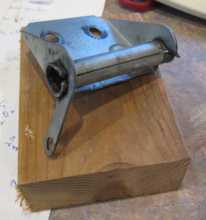
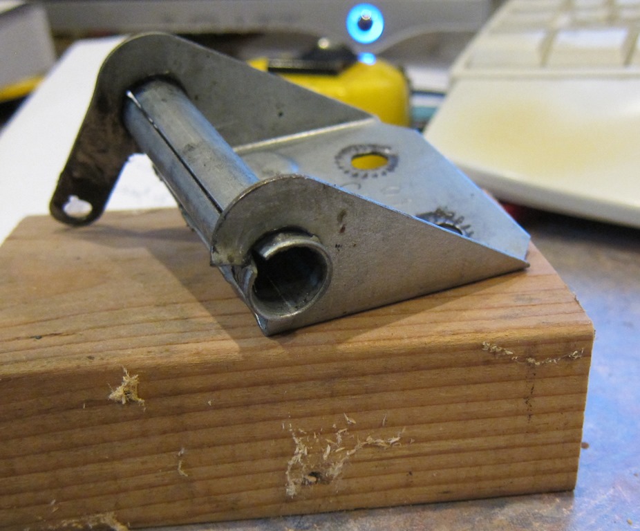
To start, I need a design that I can work from, so I started by pulling the hinge off and making a pattern:

IMG_9442IMG_9443

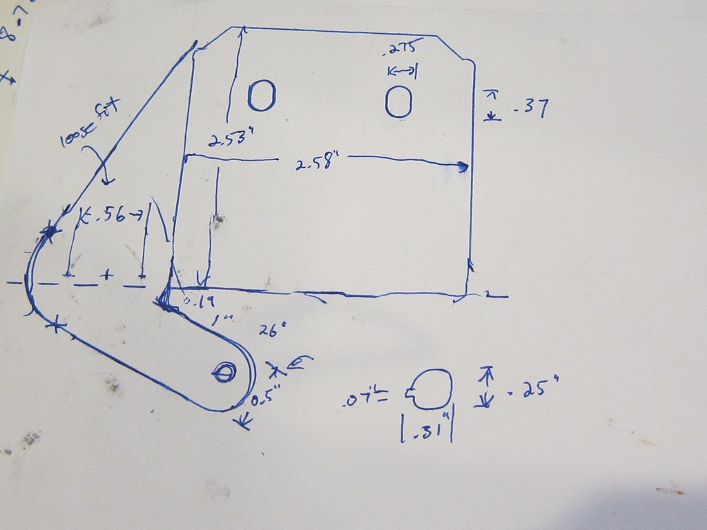
From that I did a tracing to get the format, and got out the calipers to measure holes and other parts directly. Here’s what I ended up with:

IMG_9444

At this point, my first thought was to do a quick drawing, print it out, and just transfer it to a piece of sheet metal – somehow – and then do the machining to create the piece.

I’ve done that sort of thing in the past, but the problem is that it’s hard to get the layout right, and if you mess it up you can easily ruin a lot of work. Is there a way to make it more foolproof?

CAD

The obvious solution is to do what I would call a real design. So I sat down with my drawing, a ruler, and calipers, and fired up Fusion 360.

First off, I draw the outline as two separate bodies.

image

This is pretty close, though the end of the arm is square rather than rounded. I wanted more beef on the arm, so I’ll add that in next:

image

Throw in some filets, join the old and new parts together, and we get the following:

image

Now we need some holes:

image

The locations of the holes are pulled from my drawing, and the sizes come from direct measurement of the holes in the current hinge. The little tab on the hole in the arm is there because the pin that goes through has a little tab on it for retention.

Mirror across a plane in the middle, do some cuts, do some combines, and we end up with the following:

image

I then exported that to an SVG file using the Shaper Origin plugin for Fusion. You can find the SVG here.

Manufacturing

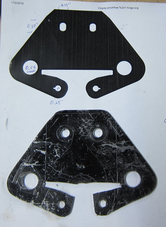
I took the design and printed it out, and then put it behind my traced design and held them up to the light to verify that things were in the right place.

The next task was to transfer that design to metal. The way that real machinists do this is to put layout dye on the metal and then scratch the design onto it. I don’t happen to have any dye lying around nor am I experienced at this.

But I do have a laser cutter. Steel is very reflective of infrared so I can’t mark it with my laser cutter, but maybe there is something I can put on it that I can ablate away?

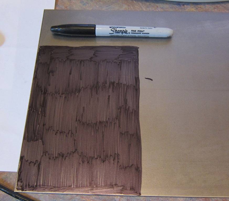
IMG_9445

So, I grabbed a sharpie, applied it to a large enough area, and went out to the laser cutter to see if I could ablate it away.

It was an absolute failure, even at powers that would easily cut 1/8” wood. Not enough IR absorption to work.

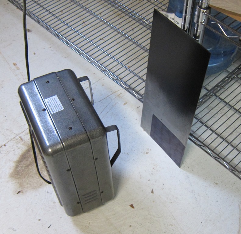
So, I grabbed a can of black spray paint I had, went outside, and put a nice easy full coat on the steel. And then put it in from of a heater to dry:

IMG_9446

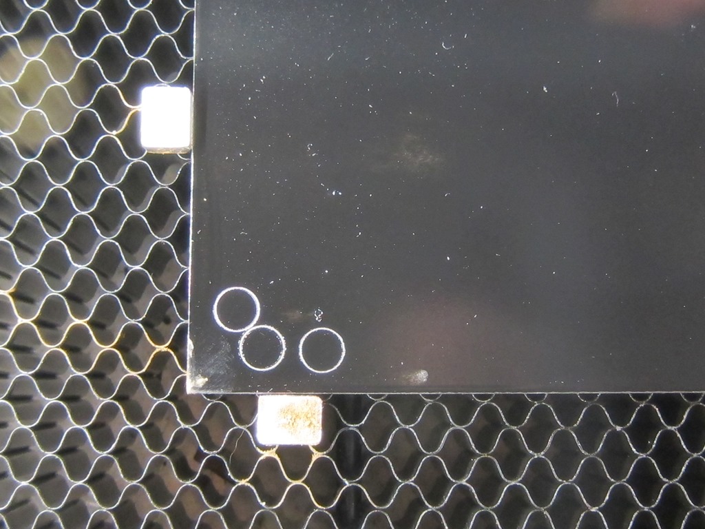
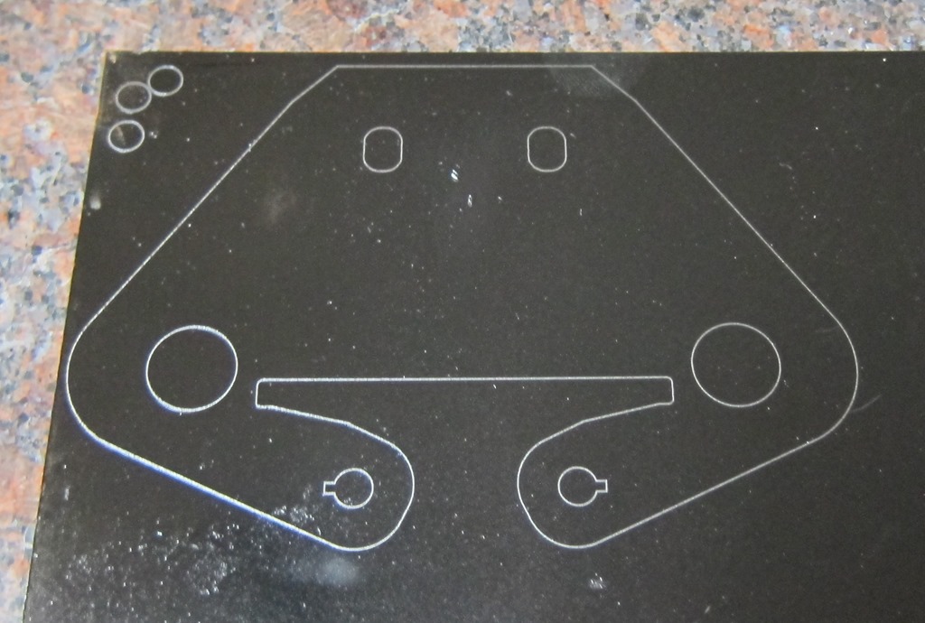
Then a few tests, and even at 25% power and my fastest speed, it still worked well:

IMG_9447

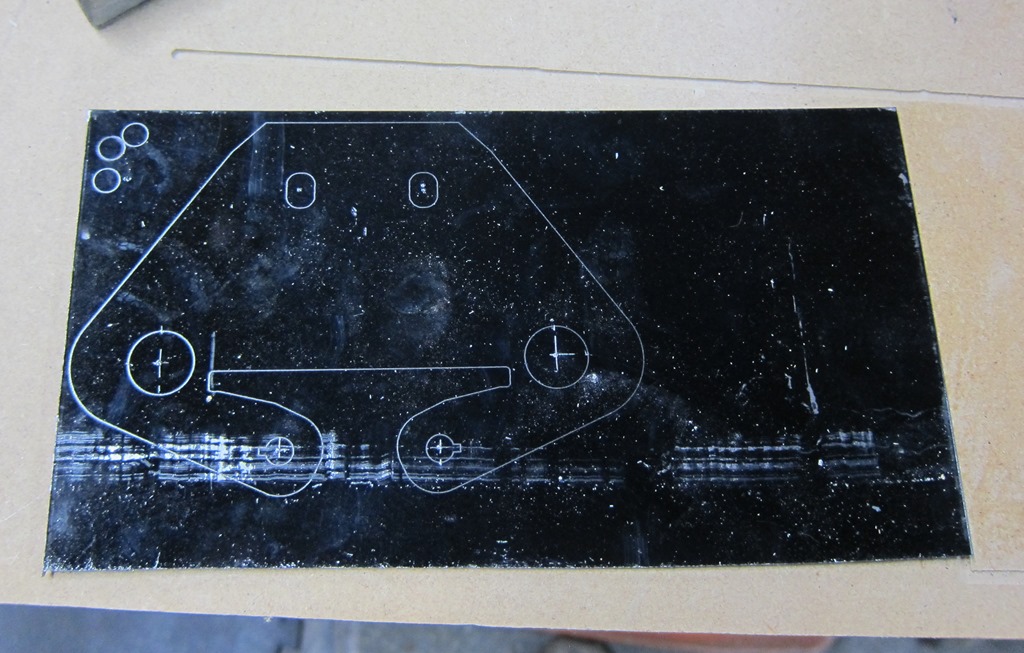
and ran the drawing:

IMG_9452

Machining

First, I cut off the part with the design and scraped the hell with the base of my jigsaw:

IMG_9453

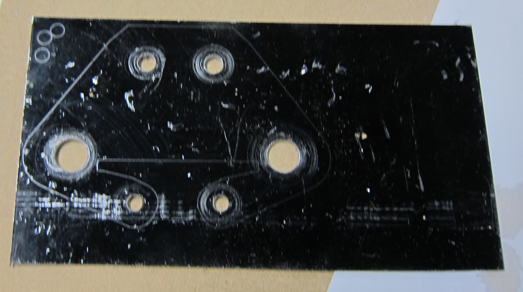
I cut the holes incrementally, starting at 1/16” and working my way up. I high recommend drilling them from the back, since if you drill them from the front the shaving will scratch off a lot of the paint.

IMG_9454

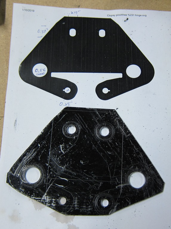
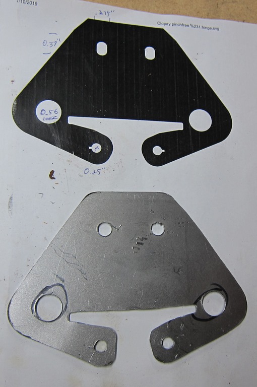
Next, I cut the outline with the jigsaw. I also scribed on some bend lines that I will need later:

IMG_9455

Starting to actually look like the drawing. I drilled a starting hole in the waste in the middle bottom, cut out the long sections with a jigsaw, and then rounded off the pieces with a grinder:

IMG_9457

A bit more cleanup with an angle grinder and a dremel, and we end up with the following:

IMG_9459

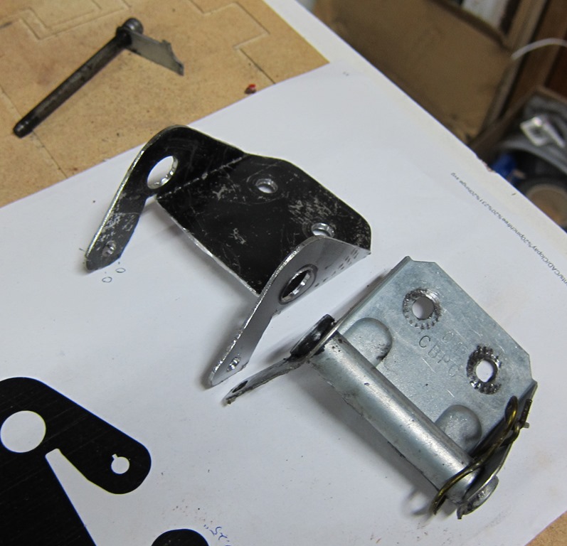
A couple minutes to fold the bracket and pull off the old one:

IMG_9463

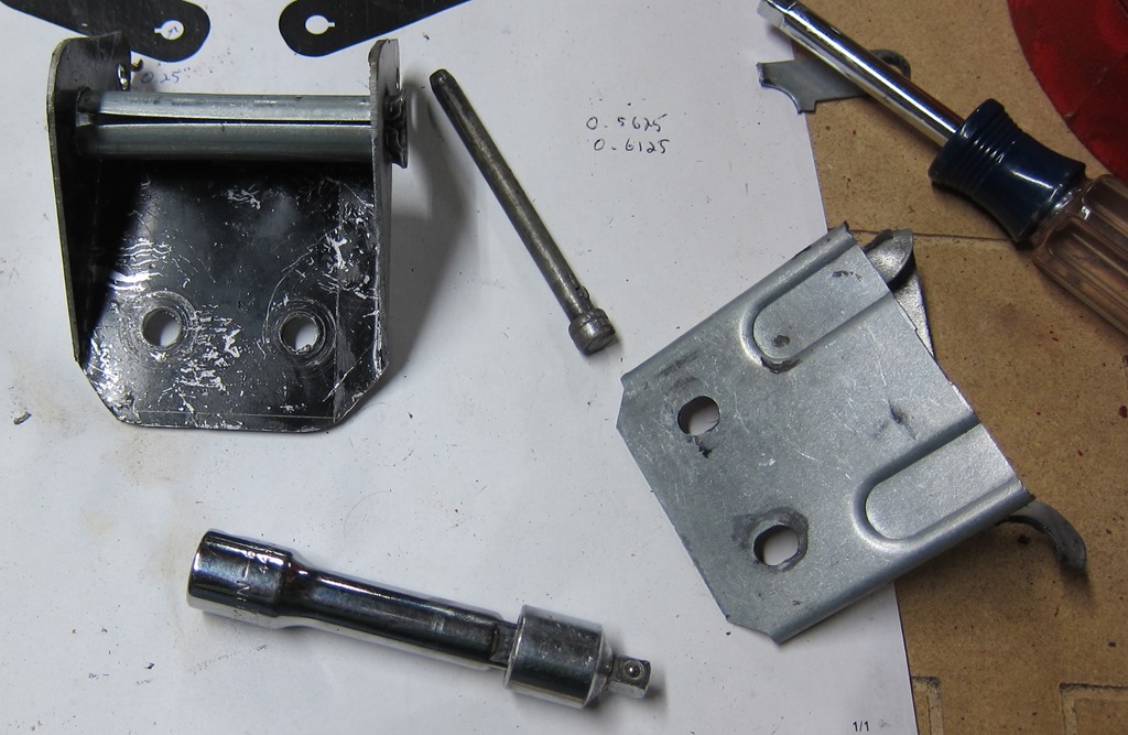
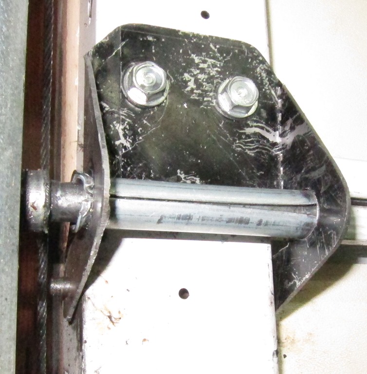
The final step is to take the tubular mount of the wheel and move it from the old mount to the new one. The tube is flared out; I unflared it by pounding it on the vice and then expanded it back out with a flared socket adapter. If I had a copper tubing flarer, that would have been a better choice. And, we’re done:

IMG_9464

And the quick reinstallation:

IMG_9468

On the left side you can see the end of the pin sticking out.


Backyard controller design #4 – Software

The controller software lives here on github. My current software development environment is Visual Studio Code with Platform IO installed on top of it. It’s quite a bit better than the Arduino IDE for my usage patterns.

I’ve done my best to build a flexible and well-abstracted design. With the exception of main.cpp, all of the C++ classes are written in the include (.h) files so that I don’t have to deal with multiple files per class.

Here are the classes and a brief description of what they do:

  • Action – takes in a textual description of an action (on, off, toggle, plus some dim levels) and converts it to a numeric value. This is a nicer pattern to use than an enum as the parsing code can live here.
  • Device – an abstraction for a device that I want to be able to control. It has a text name, a group name, an output pin, and a timeout (in 10 mS units). If you pass it a name and an action, if will implement that action if the name matches either the text name or the group name of the device.
  • HardWiredController – the physical controller (not yet built) has a group of switches connected via resistors to the input line, giving a varying voltage based on which switch is pressed. This code uses the ADC in the ESP to get the current value, figures out what button was pushed, and performs the appropriate command.
  • Main.cpp – the main setup and loop code. Mostly just delegates out to other classes.
  • MainPage.h – the text of the web interface page for the controller
  • Manager.h – the manager for all the devices. It creates an array of devices and then handles dispatching commands to them, getting status strings, handling timeouts, etc.
  • OnIfAnyDevice.h – the 12V power supply needs to be turned on if any of the lights are on. This class looks at the state of the devices passed in through the constructor and turns itself on if any of them are on.
  • StairSensing.h – The program needs to turn on the house lights if the stair lights are turned on. This code tracks whether the stair lights have been turned on and switches the house lights on and off as necessary.
  • WebServer.h – The code that handles requests for the UI page and url action commands.

The main loop runs with a 10mS delay so that every time through the loop is roughly that long; that is needed to implement the timeouts in the device class. I could have done this in a more sophisticated manner but what I did is clear and good enough for the requirement.

The Manager and Device classes warrant a bit more discussion. They are use a software pattern called “Chain of Responsibility”; there are basically 5 devices that all look alike, and the manager just passes the action through to all of them and the device that the action belongs to deals with it.

This vastly simplifies the manager class – otherwise it would have to check every string and figure out which device to pass it to – and makes it really easy to implement group devices; the “lights” group refers to all light devices. It also makes it easier to implement the OnIfAnyDevice class, which otherwise would have required special case code.


Backyard controller design #3–Board & construction

In our last installment, we were trying to decide whether to hand-wire the controller or to go with the PC board. The PC board won out handily since it only cost $13.30 for the standard 3 boards from OSHPark.

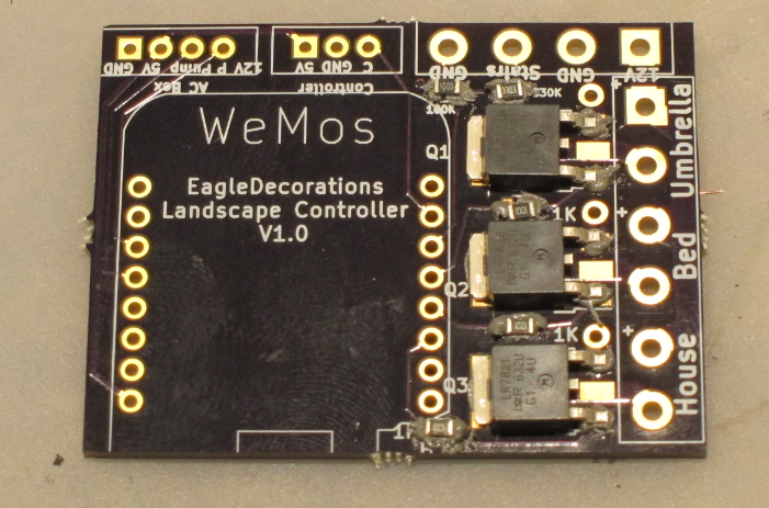
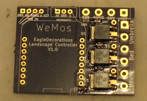
Here’s a picture of the board with populated with the 3 MOSFETs and 5 resistors. I did the solder paste application by hand since I only need to do one of these. Standard solder-paste since the MOSFETS may switch up to around 8 amps and therefore may get a bit warm.

image

And here’s a picture after the reflow. Reflow done in my Controleo 3 toaster oven reflow-er. Looks just fine.

image

One little comment: One problem I had during layout was how to connect the top pin of the MOSFETS to ground in a way that could flow enough current from the front to the back. My first design started with a number of vias, but I didn’t like it. Then I realize I had an easier solution; I just use a single through-hold pad and hand filled it with solder. It will carry far more current than I need.

Build

In my original concept all of this was going to fit inside of a double-gang electrical outlet box, but I realized that a) I’d rather mix as little low voltage and line voltage as possible and b) the box I used was only half-depth, so no room. Which argued to use a box and mount it to the house. Here’s the one I chose:

image

It’s a good size and has mounting bars. I don’t really need the gasket because I’ll be cutting holes for the wires. $11.60.

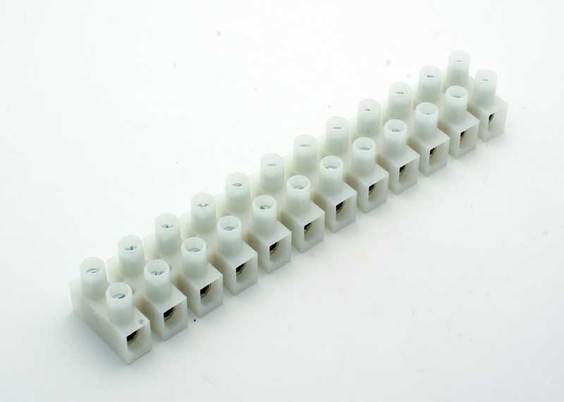
The next order of business was to figure out how to connect the big 12-gauge lighting wire to small connections on the board. I am lucky enough to have a good local Electronics store 15 minutes from my house (if you are in the Seattle area, Vetco is worth a trip), and that yielded a couple of terminal strips:

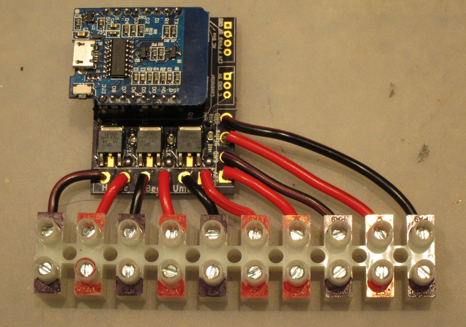
I think I bought two for $4.99 each, plus I bought some 18 gauge wire to go from the board to the strip (the big holes on the board can only support 18 gauge. Which led to this:

image

Those are all of the connections that take big wire, and the terminal strip color-coded with Sharpies.

Yes, I know I messed up the sequence; the 12V in at the lower right portion of the board really wanted to be there for each connection to the three 12V outputs. And it turns out that the wemos nodemcu layout I used was upside down, so the ESP-12 is hiding underneath the module rather than on top of it. There are female headers soldered to the board and male headers soldered to the nodemcu board. This allows me to easily remove it for reprogramming. Which was already required a time or two.

I used the same technique for the remaining controls I needed but they don’t map 1:1 to the board.

image

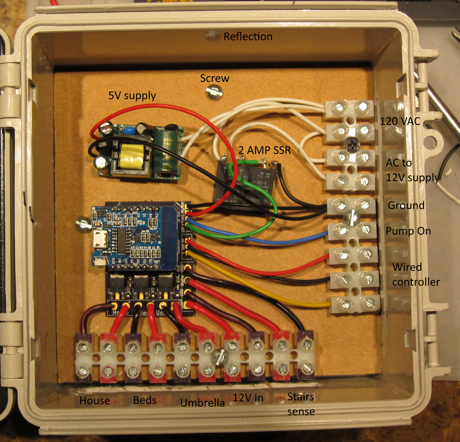
Here’s a few steps at once. I found an MDF cutoff and used that as the back of the board, and the screws that mount it also mount the terminal strips.

On the upper right terminal strip we have 120VAC coming into the box; that connects to a 5V power supply. There is a small 2AMP SSR that I had lying around that will switch on the 200  watt 12V power supply when it is needed. The “Pump on” output will connect to a similar SSR in the remote electrical box.

I did a full test of all the features, and they all worked. Well, except for the switching for the 12V power supply, which was broken by a refactoring I did in the software.

Umbrella lights

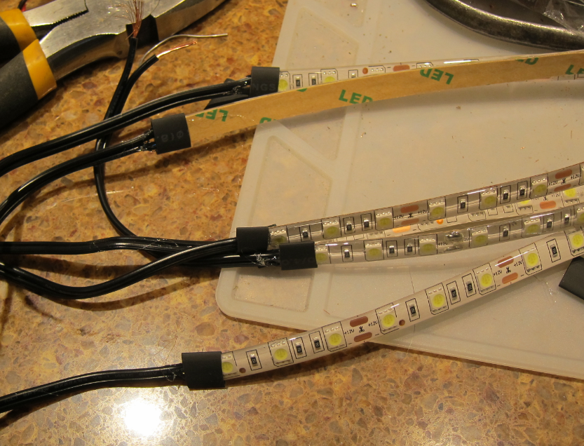
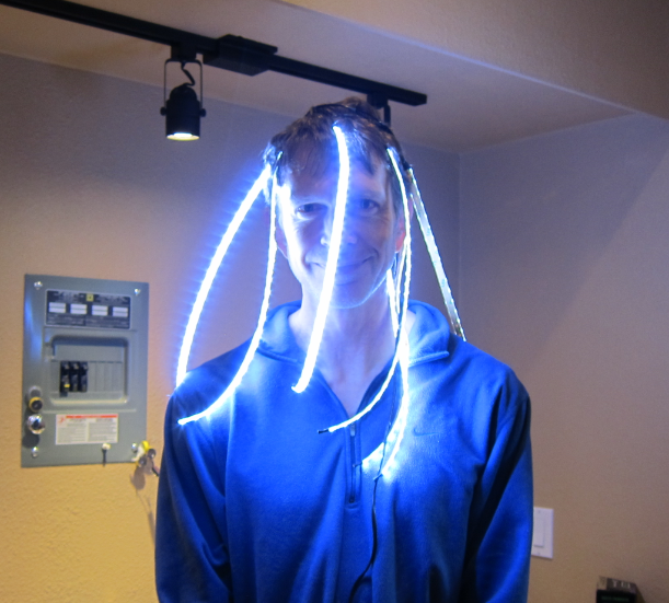
We have a shade umbrella with some chair under it, and one of the requirements was to have some light underneath it. I didn’t find any premade ones that I liked, so I bought 5 meters of 12V led strip and made my own. I made 8 strips that were 16” in length, attached wire, shrinkwrapped them, and then hooked them all together to a single supply. I only took one picture during construction:

image

But I did get this picture of them in operation:

image

Box installation

The box got installed on the wall and the various wires were hooked up.  This is under my covered kitchen deck so there is no real chance of any water getting in.

IMG_9330

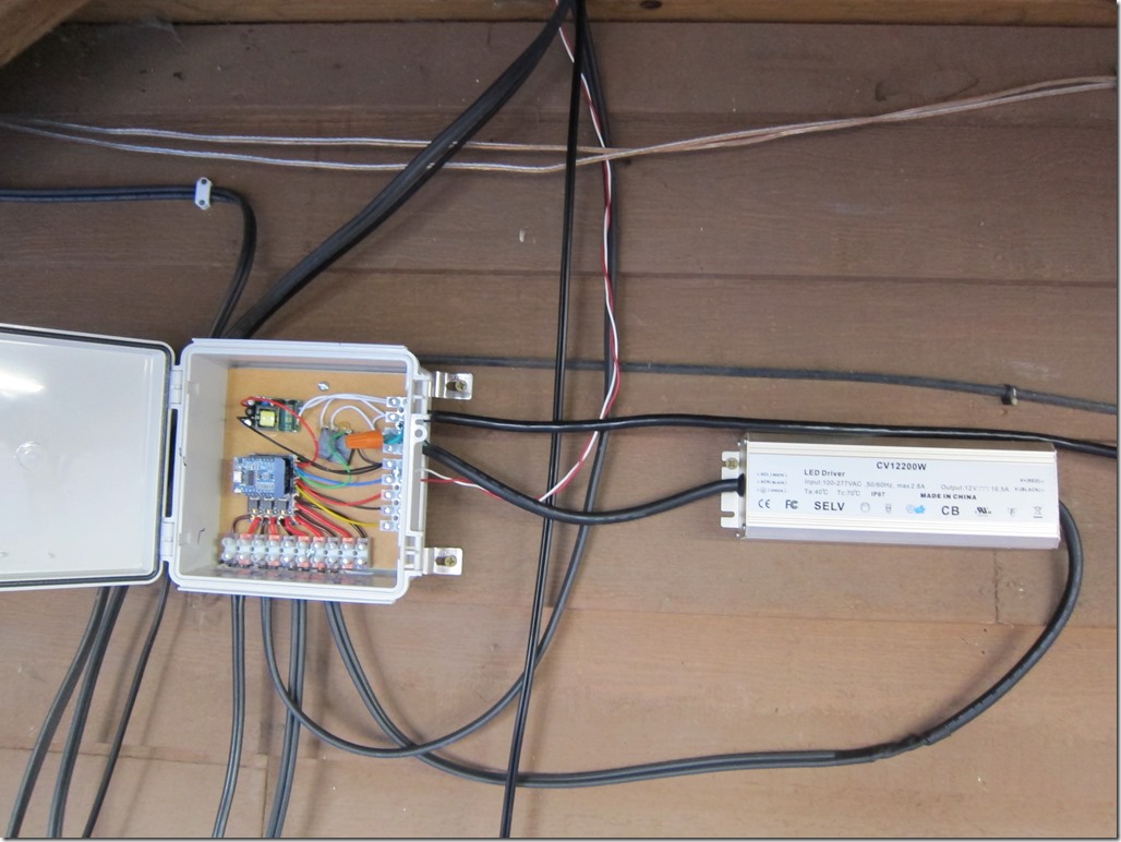
The AC comes in from the far right; that is a 15’ extension cord that plugs into a GFI with an in-use cover; directly under that is the 12 volt 16.5 amp power supply which then feeds back into the 12V input for the board. The red/white wire carries a 5V signal to the SSR in the electrical box that controls the fountain. The three main loads are hooked in along the bottom.

There are two things missing in this picture; the 12V line that used to run the stair lights is not hooked in, and the stair lights are not connected into one of the existing lines. It turns out the transformer for the stair lights does not put out 12V with no load; it puts out 17.3V. I did a conservative design on the board that would support 15V without damaging the ESP, but 17.3V was too much. I therefore built a small in-line voltage divider and used that to connect the stair lights in.

As of now, everything works fine delta one bug that I am chasing down.

I’ll write up a post about the software next.


Backyard controller design

I’ve done a lot more work on the backyard controller design and things have firmed up.

Here’s what it looks like.

First, I don’t think the 100 watt power supply I bought is going to cut it; I have 36 watts on the ground and 40 watts on the house, and we’ve added tree accent lighting, fountain accent lighting, and I think I’m going to include some existing stair lighting on this. Oh, and some umbrella lighting. That would put me close or slightly over 100 watts, and that doesn’t leave any margin for losses in the wiring or a power supply that doesn’t quite do what I think it’s going to do.

The project is going to be split into two modules.

The first will live in the duplex outlet and will consist of the SSRs to drive the pump and the power supply and a 5V power supply for the NodeMcu. I have some nice thin 2 amp SSRs that will do nicely for those two loads and I’ve verified that they work fine on 3 volts (they worked okay on 2 volts in my tests), and my current plan is to hot glue them to the back of a split duplex outlet. One outlet will be used to plug the 12V power supply into, and the other will be back wired to connect to wiring that goes to the outlet next to the water feature. I *might* go hunting for some beefier SSRS, but the good ones are unfortunately expensive and the cheap ones have a bad reputation.  So, we’ll see. The ones I have are fine for those applications but if somebody plugs something beefier things will not work well.

The 5V power supply will be just enough to run the ESP; an amp will be fine. And yes, I’m going to break code and mix high and low voltage in the same box, but I will do my best to do it sanely.

From that box I’ll run some 4-conductor cable out. It will have:

  • +5V
  • GND
  • PUMP ON
  • 12V ON

That cable will run to the second box mounted up underneath the deck. It has the following inputs:

  • 12V power (from the power supply)
  • 12V power (from the existing stair lights)
  • +5V / GND

And the following outputs:

  • 12V stair lights
  • 12V bed lights
  • 12V house lights
  • PUMP ON
  • 12V ON

Maybe I’ll add in the under-umbrella lights as a separate circuit; the extra components are cheap and it would be nice to have separate control there.

My current stair lights are controlled by a switch in the garage and a power supply there. I originally thought I’d use a 12V relay to either power them from the garage or this controller, but it’s easier to just sense the 12V in the new controller and power all of them from the new power supply.

The MOSFETS I have are IRLB8721PbF, which are reputed to be decent for logic-level switching… Let’s take a look at the data sheet:

image

What I’m trying to figure out is what sort of current I can expect if I drive them from the ESP8266 pins. My drain to source voltage is 12 volts, so I’m looking at the right side of the curve, and I’ll pick the 3.0 V curve to be conservative. And that shows me that I can get around 10 Amps, which would be 120 watts. With 200 watts planned, I’d only pull 100 watts or so, so it looks like I’m close but okay.

But… Take a look carefully at that graph. See where it says “Tj = 175 C”. Yeah, that’s hot, and it’s the absolute maximum temperature, which means I’d really need some heatsinking or other cooling. The whole point of a nice power MOSFET is that they have low R(DS) resistances and therefore don’t get very hot. Which is not true if you are only driving it with 3V. This is the “if you’re stupid” graph.

There’s another graph in the datasheet:

image

Notice this one says that it has a junction temperature of 25 degrees centigrade. Which isn’t even body temperature. But, to get that from a 3 volt drive, I can only pull 3 amps.

What that really means is that I could easily build a test circuit and have it work great with my test loads of 30 watts or so, and then install it and hook it up to a 100 watt load and it will melt. Which would be bad.

The graph gives a really simple solution; instead of driving it with 3 volts, I need to drive it with something high. Like – I don’t know – maybe the 12 volts that I already have in the circuit. The graph only goes to 10 but if it went to 12 (insert Spinal Tap reference here), we’d expect that it’s pretty much the same. And it shows that we could do upwards of 100 amps from this device in that situation.

We can’t; the maximum continuous is 62 amps, but we can easily pull the 10 amps that we need. And the datasheet also tells us that at 10V(GS), the R(DS) is 8.7 milliohms. So, at a 10 amp current, that means the voltage across the MOSFET will be 0.087 volts, and it will dissipate 0.87 watts. A bipolar transistor here would drop 0.6 volts and dissipate 6 watts, which you would definitely need a good heatsink for.

MOSFETS do see increases in R(DS) as they get warmer. I am *probably* okay, but I’ll also probably put a small heatsink on the MOSFETS anyway and do a little testing overnight to see how they are pushing that much current. Or I could do the thermal calculations to see how much junction temperature rise I can expect.

Or… I might get lazy, and run two of them in parallel. Another nice thing that you can do with MOSFETS that is problematic with bipolar transistors. Bipolars have positive thermal coefficient, so if one gets hotter it pulls more current and things rapidly go downhill. MOSFETs does the offset, so you can generally put them in parallel with no problems.

So, how do we switch it with 12V? There are numerous MOSFET gate drivers out there that are designed not only to use a higher voltage but push enough current to be able to switch quickly; MOSFETS do not technically draw current but they do have gate capacitance so you need to pull some current to get them to switch quickly. That’s really important if you are building something like a switching power supply that you are switching at a relatively high frequency, but for my application, all I need is on and off and it doesn’t have to switch particularly quickly.

So, I’m going to go old school and use a small signal bipolar transistor to switch the gate.

image

The schematic comes from here. It’s really simple; when the logic input is low, the transistor won’t be conducting and the pull-up resistor will pull the gate high, turning on the MOSFET. Turn the transistor on by flipping the logic input high, it pulls the gate to ground (well, to 0.6 volts, which is close enough), and the MOSFET will turn off. It does invert the signal, which is a bit inconvenient but not really problematic in this case, as the 12V is only there is the power supply is turned on.

Pretty much any NPN transistor will do; I have some metal cased 2n2222s in my box, so that’s what I will use.

The only remaining part of the hardware is the sensing circuit for the 12V coming from the current stair light power supply. That’s pretty simple; take the 12 volts in, run it through a simple voltage divider, and I’ll get 3 volts to feed to the ESP.

All this is going to get hand-wired on a breadboard; there’s no reason to do a PC board for this application. I think the connections will all be screw-terminal barrier strips as they work well with the beefy 12 gauge wire for the low voltage lights.

I’m also going to build a small remote that you can use inside so you don’t need your phone to do the switching.

Software

The software will be based on the ESP8266WebServer class, with a simple method to query the current state and separate methods to do the switching. I’ll do turn on, turn off, and toggle methods to provide some flexibility.

I recently switched to VS Code and Platform IO; it took some futzing to get it working, but the experience is so much better than the arduino IDE, and it knows how to create an ESP project that works out of the box. I have the bare-bones http server running for this; I don’t expect the full code is more than a day’s work if that. Oh, and I’ll do a web-page interface as long as I’m doing it.

I haven’t done anything on implementing the advanced functions based on sunset times etc., though I will probably implement auto-off for both the fountain and the lights.


Backyard controller requirements…

We’re in the process of doing some new landscaping in our back yard, and that involves a small fountain and some landscape lighting. Which of course brings up the question obvious question:

How are you going to control the fountain and the lighting?

Here are some initial requirements:

  1. There are three separate circuits of control; one for the fountain, one for the landscape lighting in the main beds, and one for the new general purpose lighting that will be mounted under the second floor eaves (the current lighting is big floodlights that provide really harsh illumination.
  2. The fountain is 120VAC; the landscape lighting is going to be low voltage.
  3. We need an easy way to turn each of them on and off.
  4. We would like to be able to have them function automatically on some sort of schedule.
  5. It would be nice if the schedule is tied into our light dark cycle automatically; I am far too lazy to remember to adjust them by hand.

The main controller will be based on a – no surprises here – an ESP8266 NodeMCU controller running a hacked-up variant of my animation software. The landscape lighting is going to be LED, which gives the following control requirements:

  • Two AC circuits – one to control the fountain, and one to control the power supply for the landscape lights.
  • Two DC circuits to control the two landscape light circuits independently.

The AC control will be done with a couple of solid state relays that I salvaged out of earlier holiday light projects. The DC control will be done with some nice power mosfets. I should be able to drive both directly from the controller.

All of this needs to fit in one half of an outlet box. I’m not sure the form factor; I’m thinking that I’m going to 3D print a box for the electronics, but how it fits into the duplex box is tbd. I *might* put override switches on the box so that if you want to you can just press a button to turn the lights on for an hour.

And you can take the underground conduit for the pump outlet and the wire for the landscape beds as “already implemented”.

Here are the parts that have already shown up:

A 100 watt 12V DC power supply. It claims to be IP67 waterproof. The “6” means that it is “Dust Tight – No ingress of dust; complete protection against contact”. The “7” means “immersion up to 1m – ingress of water in harmful quantity shall not be possible when the enclosure is immersed in water under defined conditions of pressure and time (up to 1 m of submersion)”.

IP67 rating is impressively good. If it were true, I could drop this puppy into the fountain reservoir and it would keep running…

Alas, it is unlikely to be true; the ratings for much of the stuff out of China are hit and miss, with a bit more on the “miss” side of things. Which is why it’s going to be mounted up under the kitchen deck where water won’t be able to get to it.

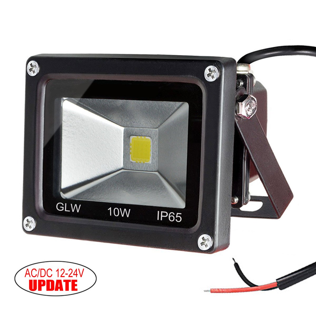
I should call these “ubiquitous 10 watt low voltage LED lights”. I have a bunch of these at my cabin, and they are pretty well made; nice heavy aluminum housings to get rid of the heat, decent mounting options. This go about 18’ up in the eaves to project a nice smooth light down on the yard. I bought 4 of them.

Image result for leonlite pathway garden light

These are the pathway lights. I spent a lot of time trolling the chinese marketplace sites (aliexpress/alibaba etc.) looking for some decent lights that were cheap. What I found is that you can either buy high end lights that are $45 each, or you can buy part of an endless supply of really cheap and crappy solar lights, but nothing in between. So I settled for these from Amazon. The Amazon product is not linked because it has changed underneath to some other lights; suffice it to say that I bought 12 of these for about $13 each. These will be spaced out in the beds to make them look all pretty-like.

Astute readers will note that I’m using 36 watts for the pathway lights and 40 watts for the floods (or only 30 if I only put up three). That leaves me about 25 watts to spare. Some may go to accent lights on the north fence, and others might go for some lighting to help get to the hot tub. If I was smart, I would have gone bigger than 100 watts, but that can be replaced if necessary later on.

This is a nice little power MOSFET that will be switching the landscape light circuits. Why this MOSFET? Well, let’s look at the datasheet.

First off, MOSFETS are far nicer to use to switch loads than bipolar transistors. Bipolar transistors have significant downsides; you need quite a bit of current to switch big loads (the overhead lights will be about 3 amps) or you need darlington transistors, and because of the fixed collector/emitter voltage drop, you lose a lot of energy in the transistors, and they get hot.

This little MOSFET will happily switch 44 amps @ 10 volts and 100 degrees C, which is *way* more than it will ever see. It will switch 3 amps with 3 volts on the gate and 11 amps at 3.5 volts; the ESP runs at 3.3 volts so it will be enough to switch the current I need (if I needed big current, I’d need a bipolar driver in front to push the voltage higher). And – like most power MOSFETS – it has very low resistance between the drain and source (8.7 milliOhms with 10 volts on the gate). What that means is that it dissipates almost no energy as heat when on, and I can run it without a heat sink; it will at most get very slightly warm. And it also means I’ll send a full 12 volts out to the lights.

I guess I could also show the big 200’ roll of landscape cable. In the old world of incandescent lights, I would have needed to power these lights with a loop or maybe multiple wiring runs; in this world, the floods have their own power supplies so the voltage to them isn’t critical and the path lights don’t pull enough power to result in much voltage drop.

For the box connections, I’m thinking I will probably go with some molex connectors; that gives me a fairly safe way to hook up the AC to the power source and that way I can disconnect the whole module.


Back yard landscaping

A few years, we paid some landscapers to do some work on our back yard; they did a nice paver patio and walkways, evened out the slope, and re-sodded the now elevated lawn.

There were, however, a few issues.

They used big landscaping blocks for the back of the beds, so there wasn’t much space for the plants in the beds, nor was there enough height to have a reasonable amount of soil, nor was there a barrier to contain the mulch. So, they didn’t work as well as beds.

And all we had was beds, so the yard wasn’t very interesting.

Oh, and we had one more issue; the decent back fence we put up was now about 12” below the current grade, which is just weird.

This summer, we are finally getting around to fixing those issues; this is partly to realize the design we had our landscape architect do, and partly to add in the things that we wanted. I’m too lazy to find the real before pics, so you’ll need to settle for “early in the process pictures”.

IMG_9268

This one shows the lovely back planting bed and the weird fence. Careful observers may be able to see some of the blocks we are using in this picture. The concrete bricks on the back are to deal with a level problem; the pavers are about 2” higher than the row of blocks that make up the back edge, so the 2 1/4” thick grey pavers make up the difference. They will not show in the completed project, so we went with the cheapest ones we could find.

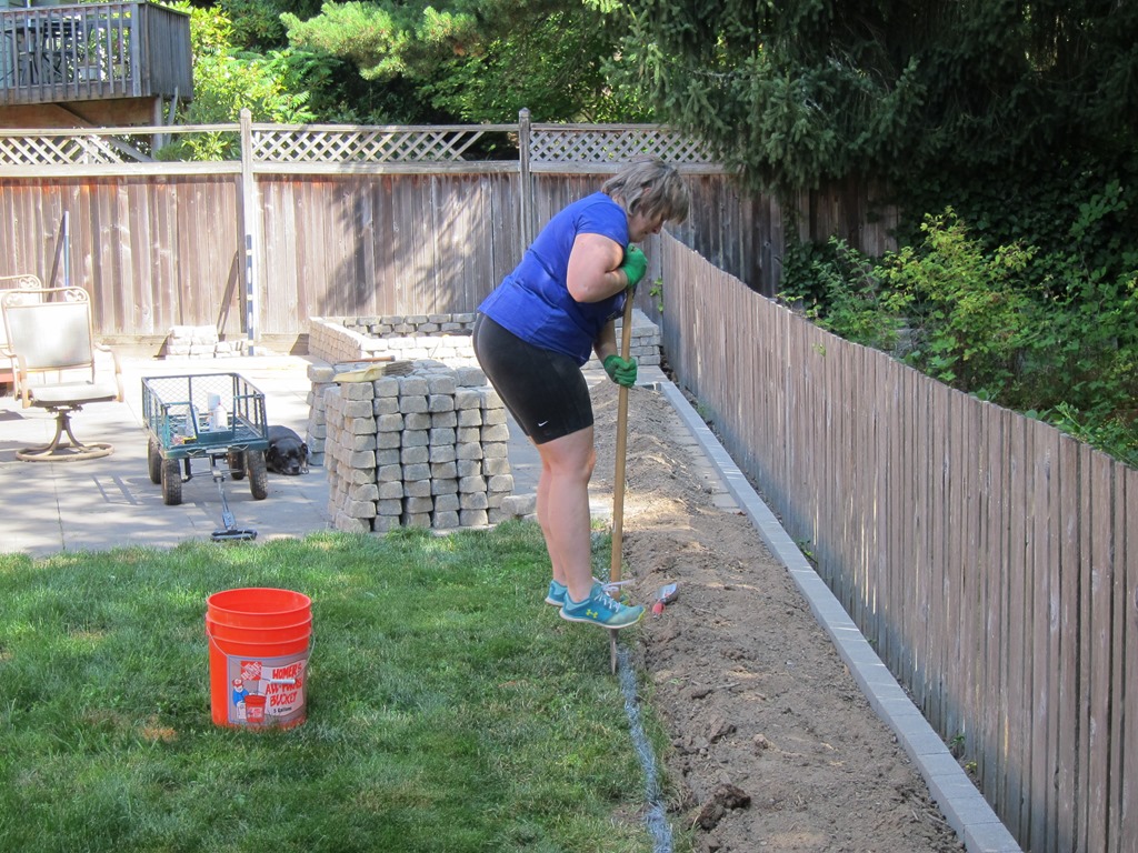
I don’t have any pictures of moving blocks; suffice it to say I moved 700 blocks @ 8 pounds each, or 5600 lbs of blocks from the driveway down the hill into the back. And 240 of the bricks.

Here’s a rough drawing of what we’re aiming for:

image

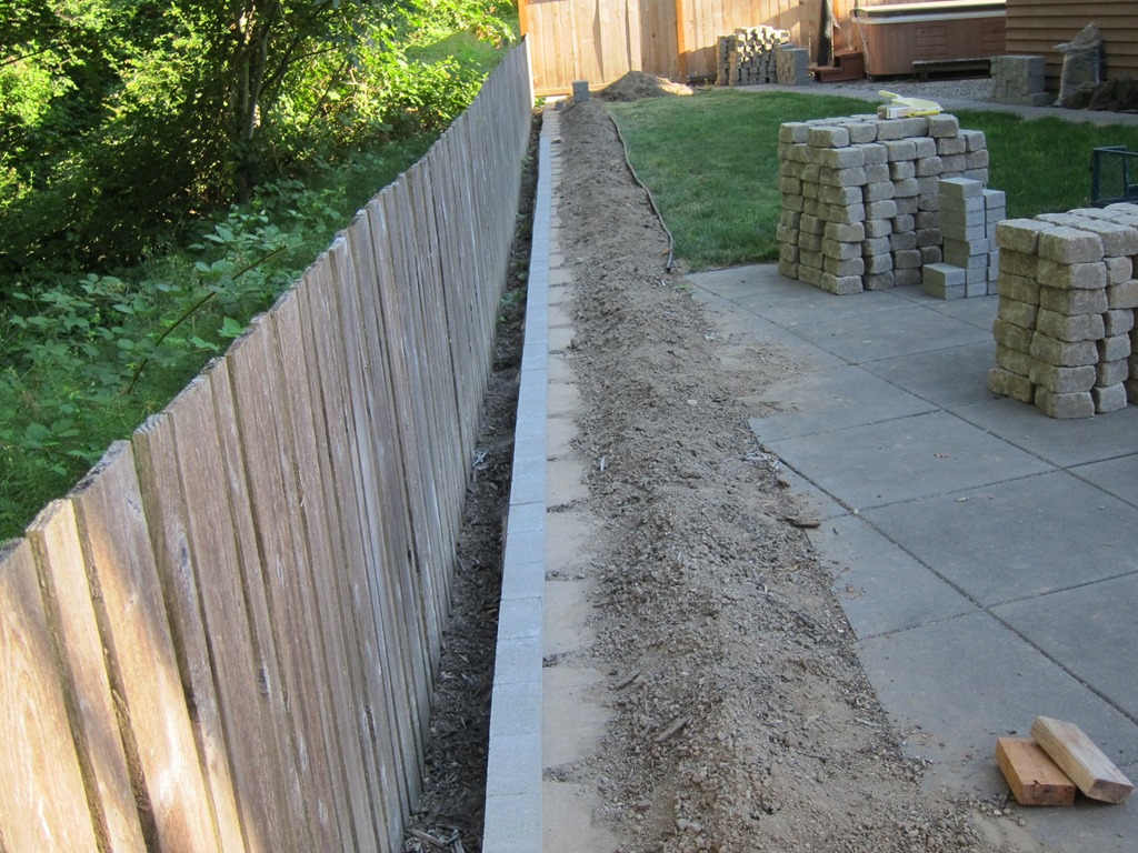
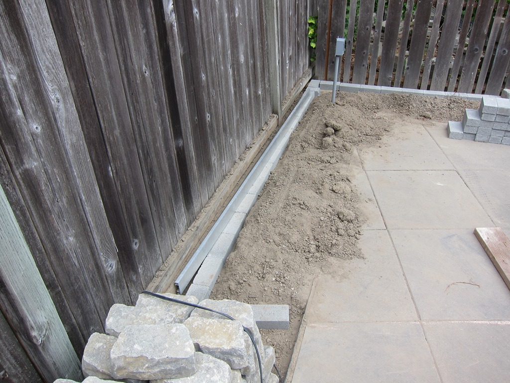
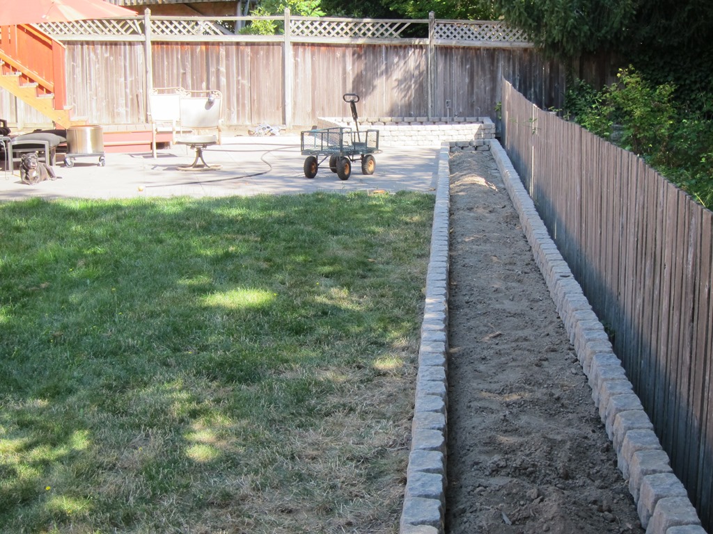
On the left side the big bed will partly cover the corner of the patio and partly be in the dirt. that required me to get a nice line of concrete bricks for the blocks to set on. It looks like this:

IMG_9265

I’ll talk more about how I achieved that soon.

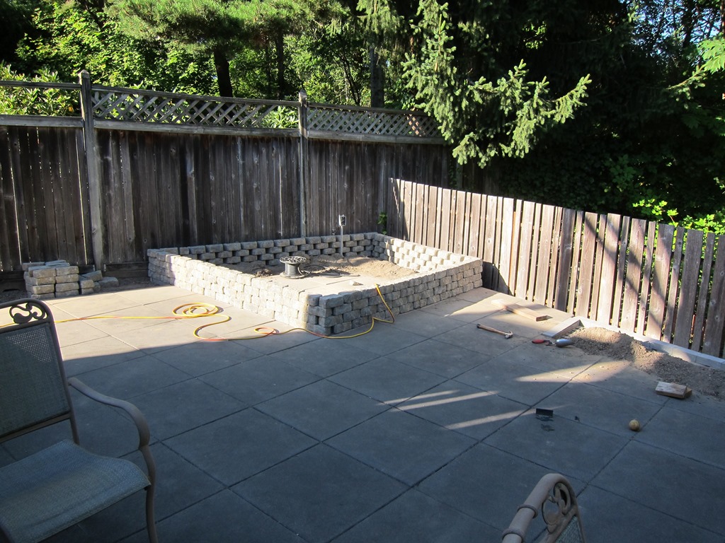
And then it’s merely a matter of laying the blocks out where you want them, and a small bit of block cutting with a 7” angle grinder and a masonry wheel. It looks like this:

IMG_9266

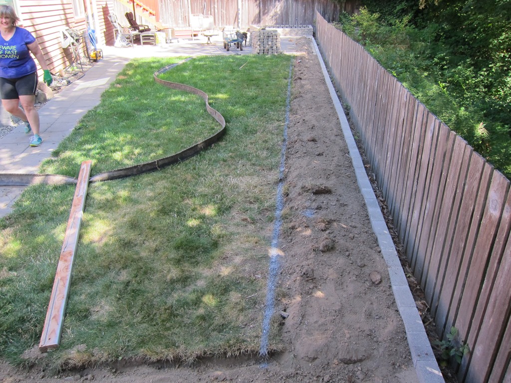
Over to the big bed. We need to cut the grass back a bit for the bricks to fit. The front of the bed is measured from the bricks next to the fence, an old 2×4 is used as an edge, and a line was painted in the grass.

IMG_9269

The project lead spent a few minutes cutting the grass away.

IMG_9270

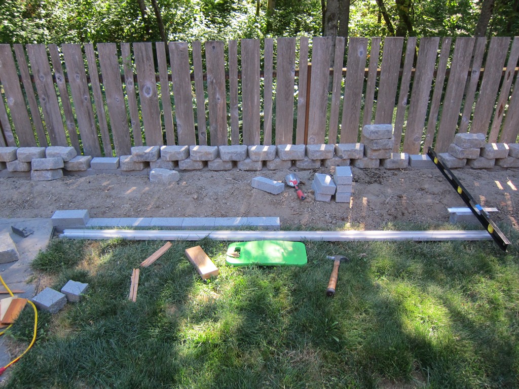
Then it’s time to set the bricks. The appearance of the final wall will depend highly on how well the bricks are set; the top of each brick needs to be in the right location (x & y), the right height (z), and also be in the right plane left to right and front to back. Here’s how I did it:

IMG_9274

The block on the far left is set to be planar with the patio and the right distance from the extra block on the back. That is one reference.

The second reference is on the right. That stack of two blocks is adjusted so the front face is the right distance from the back block, level to the back block at both the left and right ends. And then the top of the block needs to be planar with the bottom of the level and the long straight edge sitting on the left block. That takes a few iterations to get right, so 10-15 minutes to get a guide block in.

And – because they need to stay in those positions – each block has to be beaten in place with a hammer and a block of wood to compress the soil underneath.

Once the reference is, then it’s merely a matter of placing each block and using the straight edge to make sure it is where it needs to be. Along the whole length most of the bricks are less than 1/16th off on any dimension. Yes, that’s probably overkill, but getting them to 1/16th isn’t much harder than getting them to 1/8th, and it makes the landscape blocks sit much better.

There’s about 40’ of blocks to set along that bed plus another set around the right planter. So, it took quite a bit of time – probably 6 hours just on that part. But, eventually, you get them all done, you can put the landscape block on top, and you end up with a bed that looks like this:

IMG_9281

Which is honestly pretty damn straight.

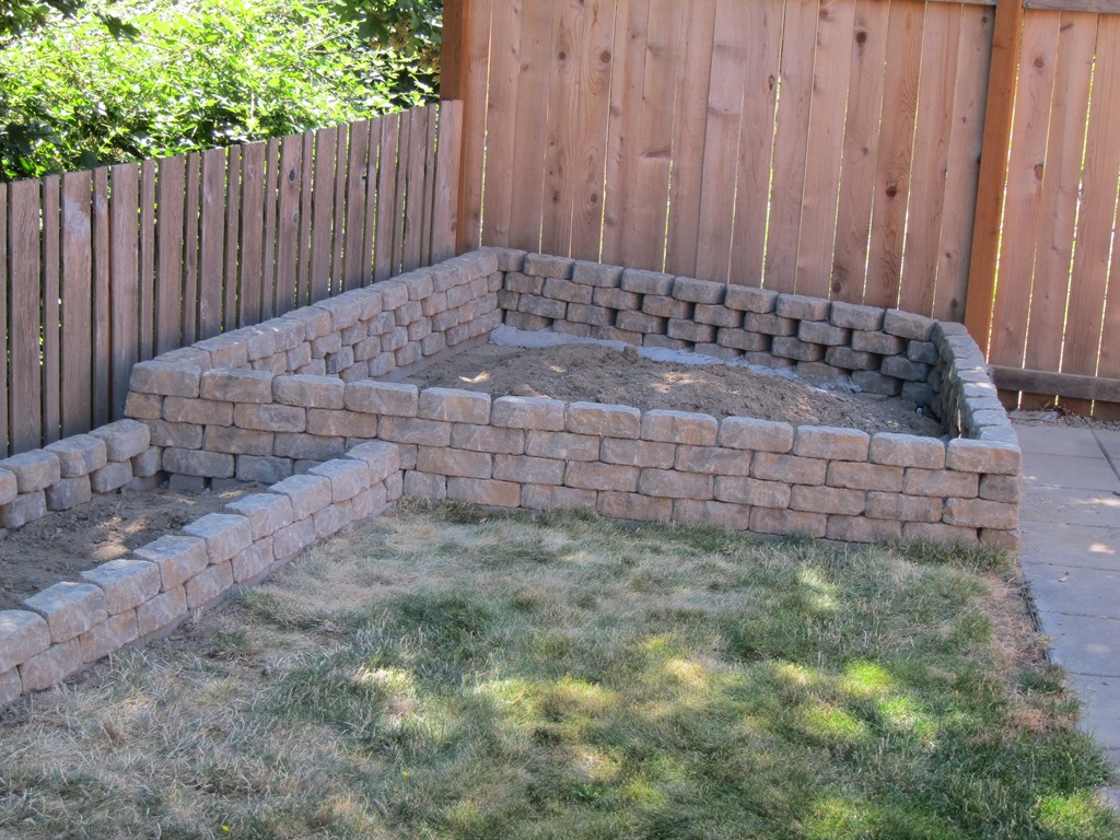
Which takes us to the right corner bed:

IMG_9280

I’d like you to pay attention to how nicely the back bed and the corner bed blocks are woven together. And I’d like you to ignore the wall next to the fence.

We basically had a problem; the blocks the landscapers put in on the fence side are higher than those along the back, so we needed to adjust. I ended up doing the whole bottom row in mortar so I could deal with the 2” difference across the thickness. It came out okay.

The day after I dog that done, I realized that the right thing to do was to put the blocks on that wall flat without bricks, and then taper from a brick down to nothing along the *back* wall next to the fence. That is the proper thing to do and I have another bag of mortar, but the project lead assures me that nobody will notice once we get the bed planted. If we need to redo it later, it will be simpler.

That’s the current state.

The future will bring soil, drip irrigation (partly in; you can see a connector in the last picture if you look closely), landscape lighting, mulch, and plants.

The fence will be elevated to be a bit higher and moved closer to the blocks. The mysterious art will be installed.

And if you think that this project wouldn’t include some custom electronics, then you don’t know me very well…