Monthly Archives: August 2019

Write and debug your Arduino programs on your desktop part 3: Fading

In the first post I said we would be doing a Larson scanner, and all we’ve done so far is make a light that goes back and forth in different colors. That is cool and all, but what about the FADING!

In standard Larson scanner, this is pretty easily done; you just need a way to go backwards for <n> steps and then you just write the bright color at the current spot and then dim it as you go backwards. With the color wheel, however, you would need to keep track of what the colors of the previous spots were and dim that color.

Seems like a lot of work to me.

Instead, we’re going to be building something that I think is a little cooler – a fading LED strip. Set a point to a specific color, and over <N> steps, it will automatically fade to black.

Hmm. It sounds like what we need is some code that can blend from a color to black. We already have a class that can do that – the ColorBlend class. We can just leverage that to do what we want. Here’s a test:

static void TestSingleFade()
{
     FadingLedStrip fadingLedStrip(4);
     LedStrip ledStrip;


    LedColor ledColor;


    fadingLedStrip.setColor(1, 255, 0, 0);


    fadingLedStrip.show(ledStrip);
     ledColor = ledStrip.getColor(1);
     Assert::AreEqual(255, ledColor.Red);


    fadingLedStrip.show(ledStrip);
     ledColor = ledStrip.getColor(1);
     Assert::AreEqual(191, ledColor.Red);


    fadingLedStrip.show(ledStrip);
     ledColor = ledStrip.getColor(1);
     Assert::AreEqual(127, ledColor.Red);


    fadingLedStrip.show(ledStrip);
     ledColor = ledStrip.getColor(1);
     Assert::AreEqual(63, ledColor.Red);


    fadingLedStrip.show(ledStrip);
     ledColor = ledStrip.getColor(1);
     Assert::AreEqual(0, ledColor.Red);
}

We set a color and then each time we call show(), it dims the color down. In this case, the dim count is set to 4, so it will take 4 more steps to dim all the way down.

The code for FadingLedStrip is here:

class FadingLedStrip
{
     int _steps;


    ColorBlender _blenders[15];


public:
     FadingLedStrip(int steps)
     {
         _steps = steps;
     }


    void setColor(int ledNumber, int red, int green, int blue)
     {
         _blenders[ledNumber].blendToColor(LedColor(red, green, blue), 0);
         _blenders[ledNumber].blendToColor(LedColor(0, 0, 0), _steps);
     }


    void show(LedStrip& ledStrip)
     {
         for (int i = 0; i < 15; i++)
         {
             LedColor ledColor = _blenders[i].getCurrentColor();
             ledStrip.setColor(i, ledColor.Red, ledColor.Green, ledColor.Blue);
             _blenders[i].step();
         }


        ledStrip.show();
     }
};

It keeps an array of ColorBlenders – one per LED. When we set a color, we tell the blender to immediately switch to that color, and we also tell it to blend to black of the specified number of steps.

The show() method then walks through all of the blenders and copies the color of each blender to the real strip and tells the blender to step.

Here’s a video of the final result:


Larson Scanner from Eric Gunnerson on Vimeo.


Write and debug your Arduino programs on your desktop part 2: Automated Testing

Read the previous post before you read this one.

In the previous post, I showed how to use hand-verification – and perhaps a debugger – to get your code working. That works well in many cases, but sometimes you have code that you think is going to evolve over time or code where it is tedious to do the hand verification.

The alternate is to automate that verification, using what is commonly known as “Unit Tests”.

Blending colors

The current implementation only uses red, green, and blue. It would be much nicer if it could smoothly change between colors. I’m going to be building a way to blend from the current color to a new color in a specified number of steps.

I’m going to do this implementation in small steps, using a technique where I write the test before I write the code. To start, we need to switch to a new color immediately when the user chooses zero steps.

Here’s my test code:

static void TestZeroSteps()
{
     ColorBlender colorBlender;


    colorBlender.blendToColor(LedColor(255, 0, 255), 0);


    LedColor color = colorBlender.getCurrentColor();
     Assert::AreEqual(255, color.Red);
     Assert::AreEqual(  0, color.Green);
     Assert::AreEqual(255, color.Blue);
}

The test blends to (255, 0, 255) – purple – in zero steps, so the next time getCurrentColor() is called, it should return that color.

The Assert::AreEqual() statements are verifying that the values we get back are the ones we expect; if they are not, a message will be written out to the console.

This test code lives in the ColorBlenderTest.h file.

The code for ColorBlender lives in the arduino project, and looks like this:

class ColorBlender
{
     LedColor _targetColor;


    public:


    LedColor getCurrentColor()
     {
         return LedColor(_targetColor.Red, _targetColor.Green, _targetColor.Blue);
     }


    void blendToColor(LedColor targetColor, int steps)
     {
         _targetColor = targetColor;
     }
};

When run, that produces no errors. In the next test, we’ll do the blend in one step. Here’s a new test:

static void TestOneStep()
{
     ColorBlender colorBlender;


    colorBlender.blendToColor(LedColor(255, 0, 255), 1);


    LedColor color = colorBlender.getCurrentColor();
     Assert::AreEqual(0, color.Red);
     Assert::AreEqual(0, color.Green);
     Assert::AreEqual(0, color.Blue);


    colorBlender.step();


    color = colorBlender.getCurrentColor();
     Assert::AreEqual(255, color.Red);
     Assert::AreEqual(0, color.Green);
     Assert::AreEqual(255, color.Blue);
}

The initial color should be black, and then after calling step(), it should move to the new color. When this is run, we get the following:

Assert: expected 0 got 255

We get those errors because there is no implementation to make the test work. This code will make it work:

class ColorBlender
{
     LedColor _currentColor;
     LedColor _targetColor;


    public:


    LedColor getCurrentColor()
     {
         return LedColor(_currentColor.Red, _currentColor.Green, _currentColor.Blue);
     }


    void blendToColor(LedColor targetColor, int steps)
     {
         _targetColor = targetColor;


        if (steps == 0)
         {
             _currentColor = _targetColor;
         }
     }


    void step()
     {
         _currentColor = _targetColor;
     }
};

and now, onto two steps. Here’s the test:

static void TestTwoSteps()
{
     ColorBlender colorBlender;


    colorBlender.blendToColor(LedColor(255, 0, 255), 2);


    LedColor color = colorBlender.getCurrentColor();
     Assert::AreEqual(0, color.Red);
     Assert::AreEqual(0, color.Green);
     Assert::AreEqual(0, color.Blue);


    colorBlender.step();


    color = colorBlender.getCurrentColor();
     Assert::AreEqual(127, color.Red);
     Assert::AreEqual(0, color.Green);
     Assert::AreEqual(127, color.Blue);


    colorBlender.step();


    color = colorBlender.getCurrentColor();
     Assert::AreEqual(255, color.Red);
     Assert::AreEqual(0, color.Green);
     Assert::AreEqual(255, color.Blue);
}

and the updated code:

class ColorBlender
{
     float _red = 0.0F;
     float _green = 0.0F;
     float _blue = 0.0F;
     float _redDelta = 0.0F;
     float _greenDelta = 0.0F;
     float _blueDelta = 0.0F;


    LedColor _targetColor;


    public:


    LedColor getCurrentColor()
     {
         return LedColor((int) _red, (int)_green, (int)_blue);
     }


    void blendToColor(LedColor targetColor, int steps)
     {
         _targetColor = targetColor;


        if (steps == 0)
         {
             _red = _targetColor.Red;
             _green = _targetColor.Green;
             _blue = _targetColor.Blue;
         }
         else
         {
             _redDelta = (_targetColor.Red – _red) / steps;
             _greenDelta = (_targetColor.Green – _green) / steps;
             _blueDelta = (_targetColor.Blue – _blue) / steps;
         }
     }


    void step()
     {
         _red = _red + _redDelta;
         _green = _green + _greenDelta;
         _blue = _blue + _blueDelta;
     }
};

That works. One more test to add; we should stop blending even if we go beyond the specified number of steps. Here’s a test for it:

static void TestThreeStepsAndHold()
{
     ColorBlender colorBlender;


    colorBlender.blendToColor(LedColor(10, 0, 0), 3);


    Assert::AreEqual(0, colorBlender.getCurrentColor().Red);
     colorBlender.step();


    Assert::AreEqual(3, colorBlender.getCurrentColor().Red);
     colorBlender.step();


    Assert::AreEqual(6, colorBlender.getCurrentColor().Red);
     colorBlender.step();


    Assert::AreEqual(10, colorBlender.getCurrentColor().Red);
     colorBlender.step();


    Assert::AreEqual(10, colorBlender.getCurrentColor().Red);
}

That fails on the last assert, as it keeps adding and gives us 13. I added some code and ended up with this:

class ColorBlender
{
     float _red = 0.0F;
     float _green = 0.0F;
     float _blue = 0.0F;
     float _redDelta = 0.0F;
     float _greenDelta = 0.0F;
     float _blueDelta = 0.0F;


    LedColor _targetColor;
     int _steps;


    public:


    LedColor getCurrentColor()
     {
         return LedColor((int) _red, (int)_green, (int)_blue);
     }


    void blendToColor(LedColor targetColor, int steps)
     {
         _steps = steps;
         _targetColor = targetColor;


        if (steps == 0)
         {
             _red = _targetColor.Red;
             _green = _targetColor.Green;
             _blue = _targetColor.Blue;
         }
         else
         {
             _redDelta = (_targetColor.Red – _red) / steps;
             _greenDelta = (_targetColor.Green – _green) / steps;
             _blueDelta = (_targetColor.Blue – _blue) / steps;
         }
     }


    void step()
     {
         if (_steps != 0)
         {
             _red = _red + _redDelta;
             _green = _green + _greenDelta;
             _blue = _blue + _blueDelta;
             _steps–;
         }
     }
};

All of that was written without and tested without any interaction with my microcontroller.

Doing something nice with the blender…

The blender by itself isn’t that useful; we need something to drive it through different colors. Here’s ColorWheel.h:

class ColorWheel
{
     int _stepCount;
     ColorBlender _colorBlender;
     LedColor _colors[6] = {
         LedColor(255, 0, 0),
         LedColor(255, 255, 0),
         LedColor(0, 255, 0),
         LedColor(0, 255, 255),
         LedColor(0, 0, 255),
         LedColor(255, 0, 255) };
     int _colorIndex = 0;


    public:
         ColorWheel(int stepCount)
         {
             _stepCount = stepCount;
             _colorBlender.blendToColor(_colors[_colorIndex], 1);
         }


        LedColor getNextColor()
         {
             _colorBlender.step();
             LedColor ledColor = _colorBlender.getCurrentColor();
             if (_colorBlender.isDone())
             {
                 _colorIndex = (_colorIndex + 1) % 6;
                 _colorBlender.blendToColor(_colors[_colorIndex], _stepCount);
             }


            return ledColor;
         }
};

It uses a ColorBlender, and whenever a color blender is done – which is checked through a new “isDone()” method – it will add a blend to the next color in the sequence. So it continuously cycles through the 6 main colors (Red, yellow, green, cyan, blue, purple).

It has tests:

#pragma once
#include “..\Arduino\Larson\src\ColorWheel.h”


class ColorWheelTest
{
     static void TestSingleStepWheel()
     {
         ColorWheel colorWheel(1);
        
         LedColor ledColor = colorWheel.getNextColor();
         Assert::AreEqual(255, ledColor.Red);
         Assert::AreEqual(  0, ledColor.Green);
         Assert::AreEqual(  0, ledColor.Blue);


        ledColor = colorWheel.getNextColor();
         Assert::AreEqual(255, ledColor.Red);
         Assert::AreEqual(255, ledColor.Green);
         Assert::AreEqual(  0, ledColor.Blue);


        ledColor = colorWheel.getNextColor();
         Assert::AreEqual(  0, ledColor.Red);
         Assert::AreEqual(255, ledColor.Green);
         Assert::AreEqual(  0, ledColor.Blue);


        ledColor = colorWheel.getNextColor();
         Assert::AreEqual(  0, ledColor.Red);
         Assert::AreEqual(255, ledColor.Green);
         Assert::AreEqual(255, ledColor.Blue);


        ledColor = colorWheel.getNextColor();
         Assert::AreEqual(  0, ledColor.Red);
         Assert::AreEqual(  0, ledColor.Green);
         Assert::AreEqual(255, ledColor.Blue);


        ledColor = colorWheel.getNextColor();
         Assert::AreEqual(255, ledColor.Red);
         Assert::AreEqual(  0, ledColor.Green);
         Assert::AreEqual(255, ledColor.Blue);


        ledColor = colorWheel.getNextColor();
         Assert::AreEqual(255, ledColor.Red);
         Assert::AreEqual(  0, ledColor.Green);
         Assert::AreEqual(  0, ledColor.Blue);
     }


    static void TestFourStepWheel()
     {
         ColorWheel colorWheel(4);


        LedColor ledColor = colorWheel.getNextColor();
         Assert::AreEqual(255, ledColor.Red);
         Assert::AreEqual(0, ledColor.Green);
         Assert::AreEqual(0, ledColor.Blue);


        ledColor = colorWheel.getNextColor();
         Assert::AreEqual(255, ledColor.Red);
         Assert::AreEqual(63, ledColor.Green);
         Assert::AreEqual(0, ledColor.Blue);


        ledColor = colorWheel.getNextColor();
         Assert::AreEqual(255, ledColor.Red);
         Assert::AreEqual(127, ledColor.Green);
         Assert::AreEqual(0, ledColor.Blue);


        ledColor = colorWheel.getNextColor();
         Assert::AreEqual(255, ledColor.Red);
         Assert::AreEqual(191, ledColor.Green);
         Assert::AreEqual(0, ledColor.Blue);


        ledColor = colorWheel.getNextColor();
         Assert::AreEqual(255, ledColor.Red);
         Assert::AreEqual(255, ledColor.Green);
         Assert::AreEqual(0, ledColor.Blue);


        ledColor = colorWheel.getNextColor();
         Assert::AreEqual(191, ledColor.Red);
         Assert::AreEqual(255, ledColor.Green);
         Assert::AreEqual(0, ledColor.Blue);
     }


public:
     static void RunTests()
     {
         TestSingleStepWheel();
         TestFourStepWheel();
     }
};

and that makes the Animater simpler. Here’s the running code:

#define NUM_LEDS 15


class Animater
{
     int _last = 0;
     int _current = 0;
     int _increment = 1;


    int _color = 0;
     ColorWheel _colorWheel;


    public:


    Animater() : _colorWheel(20) {}


    void doAnimationStep(LedStrip &ledStrip)
     {
         ledStrip.setColor(_last, 0, 0, 0);
         LedColor ledColor = _colorWheel.getNextColor();


        ledStrip.setColor(_current, ledColor.Red, ledColor.Green, ledColor.Blue);
         ledStrip.show();


        _last = _current;
         _current = _current + _increment;


        if (_current == 0 || _current == NUM_LEDS – 1)
         {
             _increment = -_increment;
         }
     }
};


Write and debug your Arduino programs on your desktop

Working on projects with an Arduino – or with other microcontrollers – can be a lot of fun. It can also be a frustrating experience; you write some code and then you need to wait for it to be compiled, packaged up, downloaded to your microcontroller, and then run. And when it doesn’t work, it can be difficult to figure out why it isn’t working; generally, the best you can do look at the output from Serial.println() or look at the signals on an oscilloscope, if you own one.

As a (now former) professional developer, I was sure that there was a better way, and after some experimentation I came up with the method described in these posts.

Basically, the approach is pretty simple. We are going to structure our software so that there are two discrete parts; a first part that is directly dependent on the microprocessor and libraries and a second part that is generic. The second part will contain the bulk of the code that we will be writing.

And then, we are going to use a generic C++ environment to run the code from the second part and verify that it works. Once we have it working in that environment, we can then move over to the arduino environment and test it on the real hardware.

In addition to making it easier to write and verify code, this will also break our code into parts and make it simpler to understand.

Tools

We will be using two different development environments. For our Arduino code, we need an Arduino environment – what I would call an “IDE”. I’m going to be using Visual Studio Code with the Platform IO package, but you can use the Arduino IDE if you’d rather. Both of those are free.

We will also need a desktop/laptop environment that can run C++ code. There are several good options here; I’m going to stay true to my roots and use Visual Studio Community with C++ support installed (also free) for that development, but you can use whatever environment you would like.

The project

A quick look at my blog will indicate that I am quite devoted to LEDs, so that’s what we’re going to build. Specifically a Larson Scanner:

Or at least something like that; I’m not sure we’re going to get to the dimming trail part. If you want to follow along, you’ll need a microcontroller that can run the FastLed library (I’m going to use an ESP8266 board), and a strip of WS2812/Neopixel LEDs. There’s a nice intro to using FastLED in their wiki here, and I suggest getting something working in your environment using their directions before trying to follow along.

I’ll add a note here that if you are using the ESP8266, Makuna’s NeoPixelBus is a better choice than FastLed as it has hardware support, but FastLed is more popular so that’s why I’m using it here.

First Version

All of the code lives in the LarsonScanner repository. I will try to keep my commits small and informative so you can see what the changes are.

I started by writing a quick and minimal version of the code. It looks like this:

#include <Arduino.h>
#define FASTLED_ESP8266_NODEMCU_PIN_ORDER
#include <fastled.h>


#define NUM_LEDS 15
#define DATA_PIN 3


CRGB leds[NUM_LEDS];


void setup() {
   FastLED.addLeds<NEOPIXEL, DATA_PIN>(leds, NUM_LEDS);
}


int last = 0;
int current = 0;
int increment = 1;


void loop() {
  leds[last] = CRGB::Black;


  leds[current] = CRGB::Red;
   FastLED.show();
   last = current;
   current = current + increment;


  if (current == 0 || current == NUM_LEDS – 1)
   {
     increment = -increment;
   }


  delay(30);
}

Most of this is boilerplate FastLED code. The code itself is simple; it has three variables:

  • current defines the next LED that we need to turn on
  • last defines the LED that is currently on that we will need to turn off
  • increment defines the direction we are moving with the animation

The loop code sets the previous LED off and turns the new one on, and then increments to move to the next LED. If that puts us at the ends of the strip – either LED 0 or LED NUM_LEDS-1 – then that tells us we need to start going the other direction and we negate increment to do that.

Running this code on the desktop

Our goal is to be able to run the code that we wrote – the code to do the animation – on the desktop. But we can’t do this because that code calls the FastLED library, and there’s no FastLED library on the desktop. What we will need to do is provide a way for our animation code to *use* the FastLED code indirectly rather than referring to it directly.

In software development terms, we’re doing what is called “encapsulation”; taking all of the code related to a specific operation and separating it from the rest of our code.

We will take all the FastLED code and move it into a separate class. It looks like this:

#define FASTLED_ESP8266_NODEMCU_PIN_ORDER
#include <fastled.h>


#define NUM_LEDS 15
#define DATA_PIN 3


class LedStrip
{
     CRGB _leds[NUM_LEDS];


    public:
     void setup()
    {
         FastLED.addLeds<NEOPIXEL, DATA_PIN>(_leds, NUM_LEDS);
     }


    void setColor(int ledIndex, int red, int green, int blue)
     {
         _leds[ledIndex] = CRGB(red, green, blue);
     }


    void show()
     {
         FastLED.show();
     }
};

This new class now keeps track of the details of dealing with FastLED. Note that the “leds” array has been renamed “_leds”; that is a naming convention to make it easier to know that it belongs to this class.

Our main code now looks like this:

#include <Arduino.h>
#include <LedStrip.h>


LedStrip ledStrip;


void setup() {
   ledStrip.setup();
}


int last = 0;
int current = 0;
int increment = 1;


void loop() {


  ledStrip.setColor(last, 0, 0, 0);
   ledStrip.setColor(current, 255, 0, 0);
   ledStrip.show();


  last = current;
   current = current + increment;


  if (current == 0 || current == NUM_LEDS – 1)
   {
     increment = -increment;
   }


  delay(30);
}

Better. There are no FastLED details in here, but there are still arduino details that would get in the way of using it from the desktop. Just as we took all the FastLED details and put them in a class, we will now put all of the animation details into a separate class. It looks like this:

#define NUM_LEDS 15


class Animater
{
     int _last = 0;
     int _current = 0;
     int _increment = 1;


    public:


    void doAnimationStep(LedStrip &ledStrip)
     {
         ledStrip.setColor(_last, 0, 0, 0);
         ledStrip.setColor(_current, 255, 0, 0);
         ledStrip.show();


        _last = _current;
         _current = _current + _increment;


        if (_current == 0 || _current == NUM_LEDS – 1)
         {
             _increment = -_increment;
         }
     }
};

That puts all the code in a method named doAnimationStep; we pass in an LedStrip, and it does whatever it needs to do.

Our main program code gets even simpler:

#include <Arduino.h>
#include <LedStrip.h>
#include <Animater.h>


LedStrip ledStrip;
Animater animater;


void setup() {
   ledStrip.setup();
}


void loop() {
   animater.doAnimationStep(ledStrip);
   delay(30);
}

This demonstrates quite well why encapsulation is a good thing; instead of having one main program with different things going on, we have three sections of code; the code that only deals with FastLED operations, the code that deals with the animation, and then a very simple bit of code that hooks them together. If your arduino code is getting complicated and hard to understand, using encapsulation will help immensely.

The desktop version

We are now ready to run our animation code. I’ve created a Visual Studio C++ project named “ConsoleTest” next to the arduino project. My goal is to run the code in Animater.h in this environment, and to do that, I’m going to need a different implementation of LedStrip.h. Here’s what I create in the ConsoleTest project:

class LedStrip
{
public:
     void setColor(int ledNumber, int red, int green, int blue)
     {
         printf(“LED %d: (%d, %d, %d) \n”, ledNumber, red, green, blue);
     }


    void show()
     {
         printf(“Show: \n”);
     }
};

Instead of talking to an LEDStrip, it just writes out the information it is called with to the console.

The ConsoleTest.cpp file in this project looks like this:

#include “stdafx.h”
#include “LedStrip.h”
#include “..\Arduino\Larson\src\Animater.h”


int main()
{
     LedStrip ledStrip;
     Animater animater;


    for (int i = 0; i < 30; i++)
     {
         animater.doAnimationStep(ledStrip);
     }


    return 0;
}

It includes the printing version of LedStrip in the test project, but it then includes Animater.h from the arduino project. The main() function then calls the animation code the same way the arduino code would call it. It generates the following output:

LED 0: (0, 0, 0)
LED 0: (255, 0, 0)
Show:
LED 0: (0, 0, 0)
LED 1: (255, 0, 0)
Show:
LED 1: (0, 0, 0)
LED 2: (255, 0, 0)
Show:
LED 2: (0, 0, 0)
LED 3: (255, 0, 0)
Show:
LED 3: (0, 0, 0)
LED 4: (255, 0, 0)
Show:
LED 4: (0, 0, 0)
LED 5: (255, 0, 0)
Show:
LED 5: (0, 0, 0)
LED 6: (255, 0, 0)
Show:
LED 6: (0, 0, 0)
LED 7: (255, 0, 0)
Show:
LED 7: (0, 0, 0)
LED 8: (255, 0, 0)
Show:
LED 8: (0, 0, 0)
LED 9: (255, 0, 0)
Show:

We are now able to see the calls the animation code would make to the FastLED library when it runs on the arduino and see if it is behaving as expected.

Digression for experienced developers

If you aren’t an experienced developer, you can safely ignore this section.

This technique – which I call “abstraction by include file” – likely looks a little weird. The “right” way to do this in C++ is to define a pure abstract class named ILedStrip with pure virtual functions that are then overwridden by LedStrip in the arduino code and by a LedStripTest class in the console project.

I’ve implemented this technique both my way and the “right” way, and I’ve found that the right way requires an extra interface definition and doesn’t really help the resulting code. And it requires understanding virtual methods. But that’s an aesthetic choice; feel free to make the opposite choice.

Modifying our animation…

Let’s say that we now want our animation to change colors each time it switches direction. Can we write that code and test it without downloading it to the Arduino?

Here’s my crappy implementation:

#define NUM_LEDS 15


class Animater
{
     int _last = 0;
     int _current = 0;
     int _increment = 1;


    int _color = 0;


    public:


    void doAnimationStep(LedStrip &ledStrip)
     {
         ledStrip.setColor(_last, 0, 0, 0);
         if (_color == 0)
         {
             ledStrip.setColor(_current, 255, 0, 0);
         }
         else if (_color == 1)
         {
             ledStrip.setColor(_current, 0, 255, 0);
         }
         else
         {
             ledStrip.setColor(_current, 0, 0, 255);
         }
         ledStrip.show();


        _last = _current;
         _current = _current + _increment;


        if (_current == 0 || _current == NUM_LEDS – 1)
         {
             _increment = -_increment;


            _color = _color + 1;
             if (_color == 3)
             {
                 _color = 0;
             }
         }
     }
};

Basically, it has a color variable that increments each time we switch directions, and we check that variable to decide what color to set.

By examining the output, we can see if the program is doing what we expect. Or we can use the debugger that is built into Visual Studio Community to have the program stop at any line in our code so that we can see what the values of variables are and what code is being executed. That is much much easier than trying to figure out what is going on in code running on the arduino. There’s a nice introduction to using the debugger here.

Tracking state

To verify an animation, we have to read a lot of output and keep track of which LEDs are which colors. We can make that a little easier by modifying our test LedStrip class so that it keeps track for us. First, we’ll need class that can hold the state of one LED:

class LedColor
{
public:
     int Red;
     int Green;
     int Blue;


    LedColor() : LedColor(0, 0, 0)
     {
     }


    LedColor(int red, int green, int blue)
     {
         Red = red;
         Green = green;
         Blue = blue;
     }
};

And then we can use that class in our LedStrip class:

class LedStrip
{
     LedColor _colors[15];


public:
     void setColor(int ledNumber, int red, int green, int blue)
     {
         _colors[ledNumber] = LedColor(red, green, blue);
     }


    void show()
     {
         printf(“Show: “);
         for (int i = 0; i < 15; i++)
         {
             printf(“(%d,%d,%d)”, _colors[i].Red, _colors[i].Green, _colors[i].Blue);
         }
         puts(“”);
     }
};

This generates the following output:

Show: (255,0,0)(0,0,0)(0,0,0)(0,0,0)(0,0,0)(0,0,0)(0,0,0)(0,0,0)(0,0,0)(0,0,0)(0,0,0)(0,0,0)(0,0,0)(0,0,0)(0,0,0)
Show: (0,0,0)(255,0,0)(0,0,0)(0,0,0)(0,0,0)(0,0,0)(0,0,0)(0,0,0)(0,0,0)(0,0,0)(0,0,0)(0,0,0)(0,0,0)(0,0,0)(0,0,0)
Show: (0,0,0)(0,0,0)(255,0,0)(0,0,0)(0,0,0)(0,0,0)(0,0,0)(0,0,0)(0,0,0)(0,0,0)(0,0,0)(0,0,0)(0,0,0)(0,0,0)(0,0,0)
Show: (0,0,0)(0,0,0)(0,0,0)(255,0,0)(0,0,0)(0,0,0)(0,0,0)(0,0,0)(0,0,0)(0,0,0)(0,0,0)(0,0,0)(0,0,0)(0,0,0)(0,0,0)
Show: (0,0,0)(0,0,0)(0,0,0)(0,0,0)(255,0,0)(0,0,0)(0,0,0)(0,0,0)(0,0,0)(0,0,0)(0,0,0)(0,0,0)(0,0,0)(0,0,0)(0,0,0)
Show: (0,0,0)(0,0,0)(0,0,0)(0,0,0)(0,0,0)(255,0,0)(0,0,0)(0,0,0)(0,0,0)(0,0,0)(0,0,0)(0,0,0)(0,0,0)(0,0,0)(0,0,0)
Show: (0,0,0)(0,0,0)(0,0,0)(0,0,0)(0,0,0)(0,0,0)(255,0,0)(0,0,0)(0,0,0)(0,0,0)(0,0,0)(0,0,0)(0,0,0)(0,0,0)(0,0,0)
Show: (0,0,0)(0,0,0)(0,0,0)(0,0,0)(0,0,0)(0,0,0)(0,0,0)(255,0,0)(0,0,0)(0,0,0)(0,0,0)(0,0,0)(0,0,0)(0,0,0)(0,0,0)
Show: (0,0,0)(0,0,0)(0,0,0)(0,0,0)(0,0,0)(0,0,0)(0,0,0)(0,0,0)(255,0,0)(0,0,0)(0,0,0)(0,0,0)(0,0,0)(0,0,0)(0,0,0)
Show: (0,0,0)(0,0,0)(0,0,0)(0,0,0)(0,0,0)(0,0,0)(0,0,0)(0,0,0)(0,0,0)(255,0,0)(0,0,0)(0,0,0)(0,0,0)(0,0,0)(0,0,0)
Show: (0,0,0)(0,0,0)(0,0,0)(0,0,0)(0,0,0)(0,0,0)(0,0,0)(0,0,0)(0,0,0)(0,0,0)(255,0,0)(0,0,0)(0,0,0)(0,0,0)(0,0,0)
Show: (0,0,0)(0,0,0)(0,0,0)(0,0,0)(0,0,0)(0,0,0)(0,0,0)(0,0,0)(0,0,0)(0,0,0)(0,0,0)(255,0,0)(0,0,0)(0,0,0)(0,0,0)

I find this approach to be a bit more visual and easier to understand.

That’s a good place to stop for this post. The next post will explore automated testing using this approach.

Part 2: Automated testing


Sequence Controller Part 2–Board design and MOSFET testing…

Having chosen MOSFETs, I went off to do some board design. I’m hoping this will be a very simple design; it needs to provide power to the ESP, connect ESP outputs to the driving MOSFETs, and provide connections for the loads to the MOSFETs.

Here’s the schematic:

image

On the right we have all of the LOAD outputs; we’re using N-channel MOSFETS to switch to ground, so there are 8 outputs plus a ground. Somewhat conveniently – assuming I’ve read the data sheets right – there are 8 PWM outputs on the right side and 8 on the left.

In my WS2811 extender I put both positive and negative terminals for the load on the board, but in this case I don’t have room so only the ground connections show up.

The other two 9-pin connectors – ExtOut1 and ExtIn1 – are for a feature that I’m hoping will be very cool, but it will be oh-so-easier to explain when I have boards in hand.

One question I already had was whether the ESP could put out enough current to switch the MOSFETs quickly enough. The time spent switching is time the MOSFETs spend in their linear region, and the Rds is much higher during that period. The SOT-32 package doesn’t give much opportunity for heat dissipation.

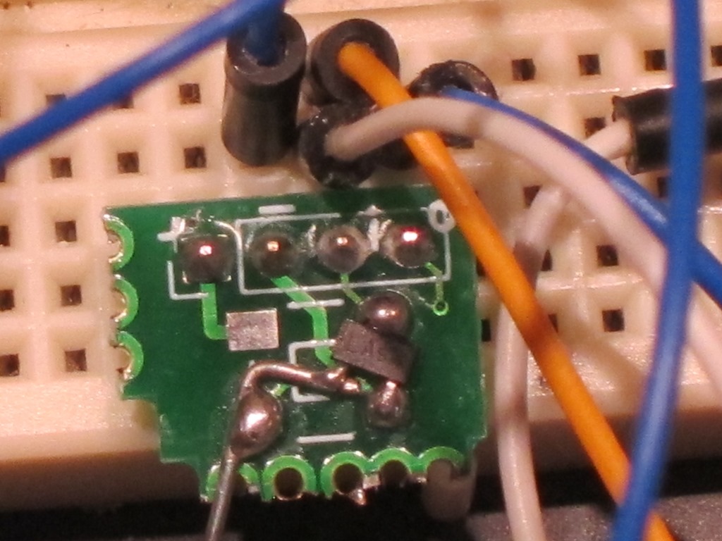
I didn’t have any protoboards to mount the MOSFET on, but I did have some WS2812 LED boards that I made. Two of the solder pads matched and I used a short wire to hook on the third one.

IMG_9584

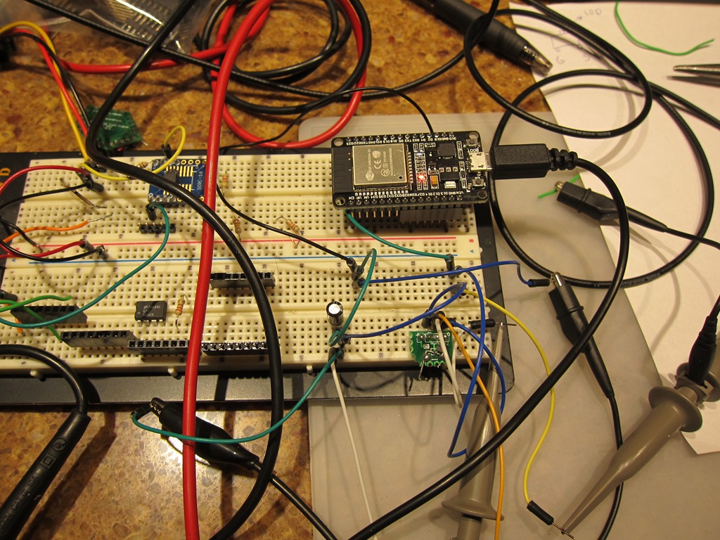
That’s wired up to the ESP.

IMG_9582

The ESP running very simple code that ramps up to full brightness and then back down.

I then needed a test load. I don’t actually have a good 2-3 amp 5V test load, so this was my first test:

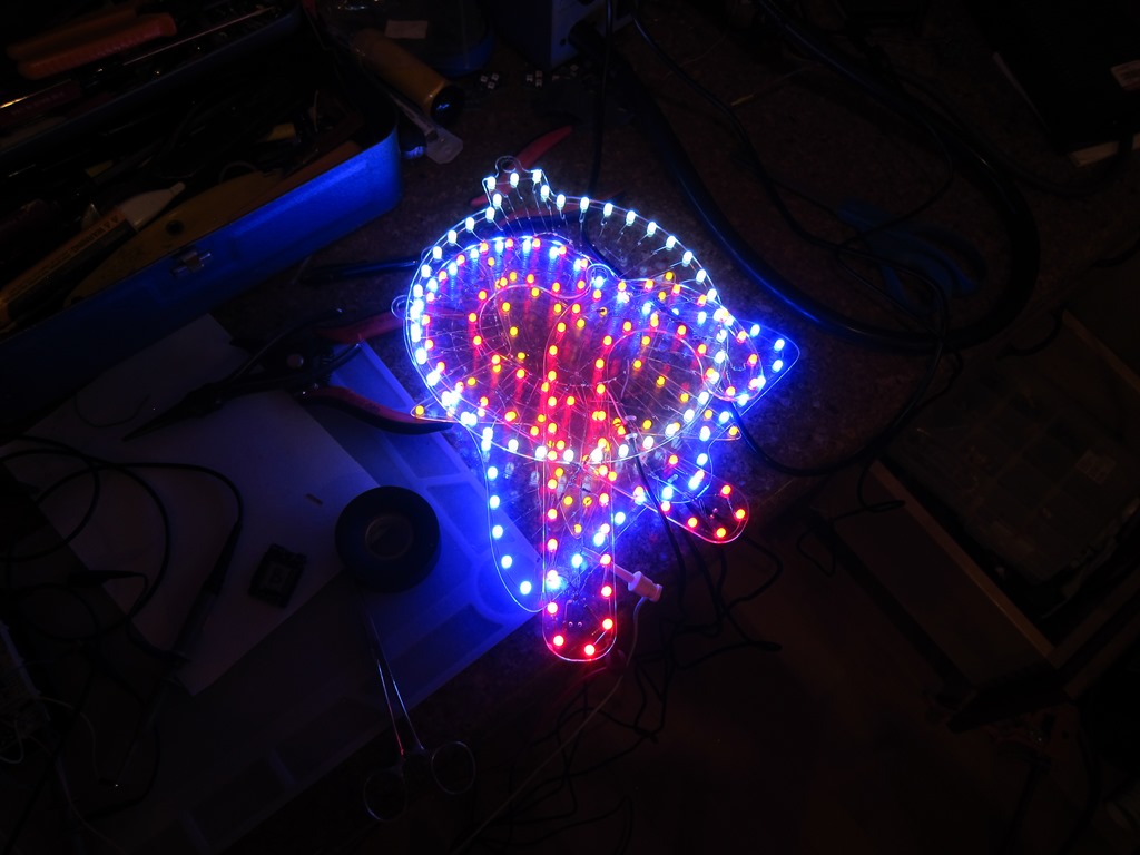
IMG_9581

That’s 5 of my ornament kits stacked on top of each other. At full brightness they are pulling just over an amp, which is my design point (more would be better). I let it ran on that for a few hours, and the MOSFET was maybe a little warmer than ambient, but barely. I threw on my 12V light bulb testing rig, and got 1.5 amps, and it was also fine with that. Two of those bulbs in parallel would unfortunately be 4 times the power which is more than the MOSFET is rated for, so I’ll need a different load to finish my testing.

I am a little concerned that the ESP may have issues driving more than 1 channel as there could easily be 8 (or 16) channels trying to change all at once. The ESP has 16 independent PWM channels and I’m thinking that if I desync the frequencies slightly (say, 500 Hz, 501 Hz, etc.), the transition points for the PWM will generally not be at the same time.

Anyway, I considered that enough of a test to do the board design. I had to do a custom component and footprint for the ESP because I couldn’t find one that matched my 30-pin DEVKIT board.

One of these times I’m going to remember to do a video of the layout process, but I usually enjoy it so much that I don’t remember.

image

The MOSFETS live at the bottom to minimize the length of the traces that carry the most current, and to put them all near the bottom. The high-current traces are 1mm wide; I could likely go to 1.5 or even 2mm but that seems like a bit of overkill for the currents I expect. The driving traces from the ESP are 0.5mm because I want to get charge into and out of the gates as quickly as possible.

There is a bit of creativity on the left side; the pins on the 9-pin connector are quite a bit offset from the ones on the ESP, so I took pin 12 and 13 and ran them up to the two top pins to make the rest easy to layout.

The board is meant to be an “undershield”; I plan on putting female headers in the 15 pin connectors of this board and those will mate with the male headers that are already on the board. The power and load connectors should probably use right-angle headers.

I spun a small order of these boards for testing.