Browsing posts in: ESP

The worst 50 watt speaker in the world…

I’ve been working on a project that I think is one of my stupider ones, and it’s time to share it so that I can move onto something that is slightly less stupid.

I build a little board that I sell on Tindie that allows you to use the WS2812 addressable LED protocol to drive bigger loads; so instead of having a tiny LED you could use spotlights in three colors.

WS2811 / WS2812 Extender

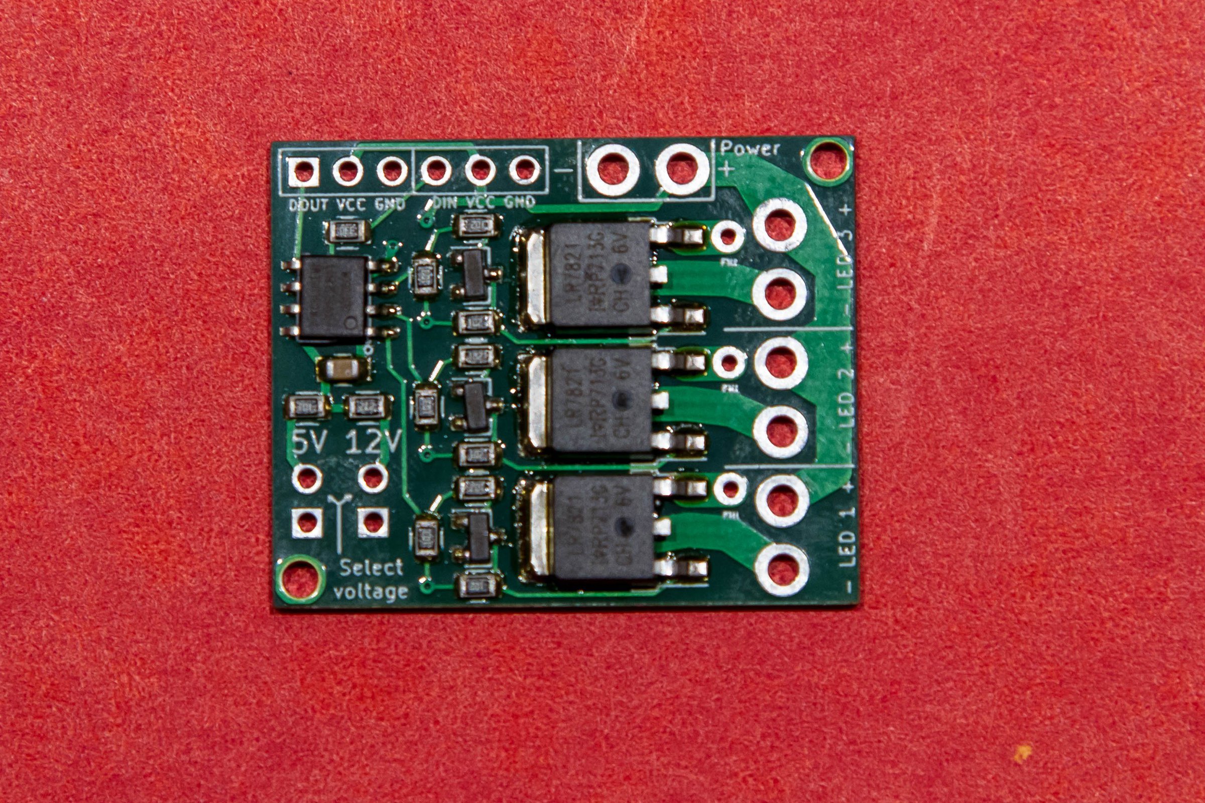
It has a WS2811 IC, some transistors to act as inverters, and then three hefty power MOSFETs to handle the load. It’s a pretty hefty circuit, but to be conservative I rate the the boards at 4 amps per channel with all three channels driven – which would be 50 watts per channel if running on 12V – or 8 amps with one channel driven.

I therefore need a test circuit to validate that these are working okay, and that’s simple an ESP8266 doing some dimming across the loads.

And for the loads, I have a series of four 12V 50 watt light bulbs – these would be used in RVs before LEDs became common. They’re nice and hefty and it’s easy to see if they are working. Here’s a video that shows the text fixture and the bulbs working:


MVI_0093 from Eric Gunnerson on Vimeo.

If you pay attention carefully – perhaps turn up your volume a bit – you will hear that the light bulbs are making a whining noise. That is because the WS2811 is running PWM at 2 Khz, smack-dab in the middle of the audible frequency range, and the light bulb filaments are vibrating at that frequency.

That was just a curiousity that I filed away, until I was testing a new set of boards and I had a thought:

What if I could change the frequency of the PWM?

And that little idea trigger a bunch of stupidity…

I dug into my supplies and found I had a bunch of unused ESP-32 boards leftover from when I ordered the 36-pin version instead of the 30-pin version.

image

I had sample code that did 16-channel PWM on the ESP-32 – the ESP-32 is almost ridiculously capable in some areas – and I ported that over to a new version, took one of my driver boards and pulled off the WS2811, wired them together, and got… nothing.

Played around some more, got more nothing. I just could not get it to work. The board would work fine when I drove it directly, but the ESP could not drive it. I also had trouble getting the LED on the board to work; it barely lit up at all. That should have been enough, but it took me an embarrassingly long time to figure out what I think is the problem…

Basically, these boards have a 3.3v regulator on it that is not up to the task. It claims to be an AMS1117, which should be a fine choice; that regulator has nice specs and can put out up to an amp of current; plenty for the ESP32. AFAICT, what it actually has is a cheap counterfeit that just barely puts out enough power for the chip to run but not to do anything useful. I could measure the outputs of the ESP and they looked fine as long as I didn’t put any load on them. I dredged a memory out of my brain that others had run into this issue, so now I’m left with a bunch of boards that don’t work, though I’m considering replacing the regulator to see if that helps.

I dug out one of my other ESP-32 boards, moved the code over, and it worked great on the first try. So don’t buy the other boards…

From concept to “music”

This section also took much longer than it should have, so I’m just going to mention the highlights…

The midicsv program is your friend if you want to convert songs into arrays of note values.

Midieditor was quite useful to simplify arrangements and fix up some of the midi notes, though the documentation is mostly absent.

Note quantization can be very useful if the midi file you download ends up with a new note starting quite a bit earlier than the note that it is replacing.

Excel is your friend when manipulating CSV files.

Midi tempo is complex. Basically, the note timing is expressed in terms of “ticks”. The header in the midi file specifies how many ticks there are per quarter note, sometimes expressed as “parts per quarter note” or PPQ. It will be something like 256 or 480.

Tempo is expressed in the number of microseconds per quarter note, and will be something like 500,000.

So, with a bit of math, you can determine:

tick time in seconds = (tempo / 1000000) * (1 / PPQ).

Then, based on the difference in ticks between when a note starts and when it ends, you can figure out the delay.

ESP-32 LEDC Fun

Conceptually, I wanted to have different PWM channels running at different frequencies. This turnout out to be far more problematic than I thought.

My first mistake was using the ESP-32 arduino HAL (hardware extraction layer) functions for the LED control subsystem. Conceptually, all I should need to do is:

  • Call ledcAttachPin() to attach a specific GPIO pin to a specific PWM channel (the ESP-32 support here is really nice).
  • Call ledcSetup() to specify the PWM frequency and resolution in bits that I wanted).
  • Call ledWrite() to set the PWM duty cycle (either 256 to turn the light off or 64 to turn it mostly on).
  • And that’s what I did. And it sorta-kinda worked in some cases, didn’t work in others. I finally called ledcReadFreq() and looked at the values I was getting back. Channels 0 and 1 were always the same frequency, but channel 2 was a different frequency. Hmm…

    After reading the non-arduino docs for the led control system, I came across the docs for ledc_set_freq(), which had a parameter named “timer_num”, and the description said “LEDC timer index (0-3), select from ledc_timer_t”.

    Ahh… There are only 4 timers that you can use, not 16. Unfortunately, the HAL abstraction gives the impression that you can set frequency individually on each control channel. You can, it just affects other channels as well. Digging into the source, I found this table:

    /*
    * LEDC Chan to Group/Channel/Timer Mapping
    ** ledc: 0 => Group: 0, Channel: 0, Timer: 0
    ** ledc: 1 => Group: 0, Channel: 1, Timer: 0
    ** ledc: 2 => Group: 0, Channel: 2, Timer: 1
    ** ledc: 3 => Group: 0, Channel: 3, Timer: 1
    ** ledc: 4 => Group: 0, Channel: 4, Timer: 2
    ** ledc: 5 => Group: 0, Channel: 5, Timer: 2
    ** ledc: 6 => Group: 0, Channel: 6, Timer: 3
    ** ledc: 7 => Group: 0, Channel: 7, Timer: 3
    ** ledc: 8 => Group: 1, Channel: 0, Timer: 0
    ** ledc: 9 => Group: 1, Channel: 1, Timer: 0
    ** ledc: 10 => Group: 1, Channel: 2, Timer: 1
    ** ledc: 11 => Group: 1, Channel: 3, Timer: 1
    ** ledc: 12 => Group: 1, Channel: 4, Timer: 2
    ** ledc: 13 => Group: 1, Channel: 5, Timer: 2
    ** ledc: 14 => Group: 1, Channel: 6, Timer: 3
    ** ledc: 15 => Group: 1, Channel: 7, Timer: 3
    */

    Ah. I’m not sure why the mapping works the way it does, but that’s the way it does, and channels 0 and 1 always use the same timer. And I think that’s a decent reason not the use the HAL, but since my code was written and I was lazy, I just mapped my channels 0, 1, 2 to 0, 2, and 4, and things were fine.

    Which finally led to me declaring success, and I can therefore offer up the following videos.

    Project video

    Here’s a project video that shows the result. The light bulbs are terribly inefficient; with 40-50 watts of input they produce a very tiny amount of sound.


    Summary

    So that’s the stupid project. The software supports 3 channels but I burned out the third channel on my board when I was having issues with the crappy ESP, and since two channels is barely discernable, there’s no reason to go farther. If you would like to see the stupid code, it is here.


    An ESP-32 Remote Control–Update and Version 1.0 case

    About 3 months ago, I wrote a post about an ESP-32 based remote control I’m building. Conceptually, what it does it allow you to press a button and hit a specific web endpoint.

    Since the introduction, I wrote some code and got a prototype kindof working – the touch inputs on the ESP32 work fine, the deep sleep works okay, but I ran into a few problems.

    First, the ESP32 can run on 3.0 volts but only kindof, and if you use two AAs their voltage drops pretty quickly to the point where the ESP stops working. Which means I needed a better power source, which means lithium based. I looked at primary (non-rechargeable) lithiums but they are also 3 volts (IIRC), I looked at lithium-ion, but 4.7 v is a really inconvenient voltage for ESPs; you need a regulator to get down there. Plus the 10850 cells are a bit big. Then I settled on LiFePo4 batteries, which very conveniently have a nominal voltage of 3.3 volts and are the same diameter (but shorter) than a AA, so they work well for packaging.

    I bought a little battery monitoring board to protect the battery, but I’ve decided to skip it for this version. So, I think I’m set for batteries.

    The second issues came up during my deep sleep testing. The ESP32 can get down to 10 uA in deep sleep, which looks great, *and* it supports “wait on touch” where it will turn on based on a touch input, which is also great. But…

    The devkit boards that I have don’t support using it that way; even with the power led removed I think I was seeing about over 10mA when the ESP was in deep sleep. Not good enough. Some people have hacked their boards to remove some of the components, but traces are tiny and the board is dense, and I gave up after a few tries. I could use a module programmer like this which pulls the dev kit components onto the programmer and leaves just the raw board, but the problem there is I need a mounting solution that lets me program the same module every time.

    What I really need is the dip part of the devkit board without any of the power supply or usb stuff and an adapter to hook that to the module programmer.

    Since I haven’t figured that out, I went with the best deep sleep approach that I know, a rocker switch. I’m thinking that will get the power use all the way down to 0 uA.

    The case

    I have some plans for the version 2.0 case, but those require a fair amount of prework and new tools, and it’s nice enough that I could really use the remote *now*, so I went with with the easy approach – a laser cut box.

    For touch points, I wanted some screw together pieces or screw studs, which I finally discovered were commonly known as “chicago screws”.

    Chicago Screws - "Flat Beveled" Design - Solid Brass (10-pack ...

    I wanted them in brass so that I can solder to them. The ones I got are 1/4” (6mm, actually) in length, which would be fine for my “real remote” design, but meant that I need to use 1/4” plywood for the face.

    I did the design in Fusion 360. This design was not one of my better moments. I did the face in 1/4” but the sides on 1/8” so they would be thinner, but it turned out that I don’t have any 1/8” plywood left; what I have is 1/10”, so I had to redo the design. Then I measured the size of the studs very accurately with my calipers and then entered the shaft length (0.235”) instead of the shaft diameter (0.165”). And the power switch was too close to the corner so the top and side wouldn’t fit. Then I cut the top piece out of a piece of 1/8” scrap, so it was too big.

    More trips back and forth than I had hoped, but it’s only computer and laser time plus a bit of wood, so it wasn’t that bad. Here’s the result:

    IMG_9719

    Which is honestly pretty nice. The labels are engraved into the wood, and all it is missing is the power LED. The current plan is to glue the sides to the front and leave the back removable for access, but it’s not clear to me how that is going to work yet.

    Video here:


    Next up will be wiring up the front panel, assembling most of the box, and then hooking in the ESP and battery.


    An ESP-32 Remote Control–Introduction

    A couple of years ago I did an ESP-32 based controller for our landscape lights and fountain. It has a nice web-based interface, if you like the way interfaces looked when HTML was young…

    image

    In addition to this web page, you can hit http endpoints directly, so you can control things with either a browser or an HTTP app on your phone. It’s a bit of a pain to dig your phone out and run an app to turn on lights, so I’ve always planned on doing a handheld controller. It’s going to be pretty simple; just a set of buttons and an app that sends requests to the actual controller.

    At least, that’s how it started…

    My original plan was to use an ESP8266 because it’s smaller and to use some normal momentary pushbuttons:

    Momentary-ON-OFF-Push-Button-Switch-Waterproof-12mm-Black-M122-Mini-10pcs

    That would have been fully functional, but I didn’t really like the way the buttons looked and I didn’t like the low-power options very much. I was looking through the ESP-32 technical manual and remembered that the ESP-32 has a touch-sensor subsystem that supports 10 separate inputs. That means I can do a cleaner-looking controller that has metal touch points rather than buttons, and the ESP supports wake on touch, so I can put the controller into deep sleep.

    Conceptual design

    Here’s a very quick drawing:

    image

    Here’s what I’m thinking for the design. There are 5 circuits to control:

    • Fountain pump
    • Bed lights
    • House lights
    • Umbrella lights (strips under umbrella)
    • All lights

    In addition, I want to be able to control the brightness of the umbrella lights in 5 steps; 20%, 40%, 60%, 80%, and 100%

    Coincidentally that requires 10 different controls, which is exactly how many touch inputs the ESP has, so that worked out well.

    The controller will be remote-control-shaped, with batteries (tentatively 2 AA alkalines) near the bottom, the ESP in the middle, and an array of touch points at the top.

    Sleep battery calculations

    There is an assertion that the ESP32 in deep sleep only pulls 2.5uA. A typical alkaline AA cell has a capacity of about 2000-3000 mAH, so if we do some math:

    Hours = 2000 mAH * 1000 (convert to uAH) / 2.5 = 800,000 H, or 33,000 days. If we could really get that, that would be 91 years on standby.

    Let’s do the calculation the other way; if we wanted batteries to last a year, that would give us:

    2000 mAH / 365 = 5mAH per day, or 228 uA of constant current. If I can hit something under that, I’ll get a year out of the batteries.

    Getting that to work is going to require me to either modify the ESP-32 devkit boards I’m using or switch over to a raw module and separate programmer, but that’s a matter for another post/video