Monthly Archives: January 2018

DLE (Globes of Fire) Pt 2

A week or so goes by, and I get a package back from allpcb, so I started building one.

Each half has a ring of 5 pentagons plus one the end, so I started hooking 5 boards together:

IMG_9044

The WS2812 LEDs are only 5mm on a side, so the whole board is roughly 15mm x 17mm. That’s tiny, and frankly working on it was a huge pain. I did this, put the boards into a box, and closed it.

Then I came back the next day and decided to have another try. Rather than connect on the outside, I decided to use a much lighter wire and connect on the inside (back) of the boards. Here’s a set of 5 with VCC and GND hooked up:

IMG_9046

Yes, that’s some *ugly* soldering, but in my defense I’d like to note that the spacing on the holes is about 0.05”/1.3mm. This then gets folded into a ring. Eventually, we end up with the top and bottom:

IMG_9050

Next, those two are soldered together with wires to carry VCC and GND between halves, and you end up with this:

IMG_9052

Next was to wire through the data ports. Basically, it starts at one face at the open end, goes around that ring, goes around the lower ring, and finally travels to the bottom. Add in some hot glue to help hold things together, and put the LEDs on, and here’s the result:

IMG_9053

That is one ugly bit of construction, and it took a lot longer than I had hoped.

IMG_9055

After soldering a few hundred WS2812s, you learn how to do it without burning them up. On the left is one face from the 3-LED version that I tested to verify the layout.

V1.1

The first version was technically a success, but only because I so cussedly kept on. I was wondering if I could make something small enough to fit in an ornament ball, and the answer is “yes”, but you really don’t want to do it.

So, it’s practically a failure.

The biggest problem is the connection between the faces; the holes are too hard to solder, and using individually-cut wires is a pain…

So, I’m going to abandon the single-LED version (kindof – more on that later) and work on the 3-LED version. I started by going with standard 0.1” (2.54mm) header spacing, and the plan is to use angled headers. The angled headers will stick out to the side, and two faces are connected by soldering the ends of the header pins together. It’s going to look a big weird, but should be a lot easier to construct.

Here’s the old design and the new one:

image

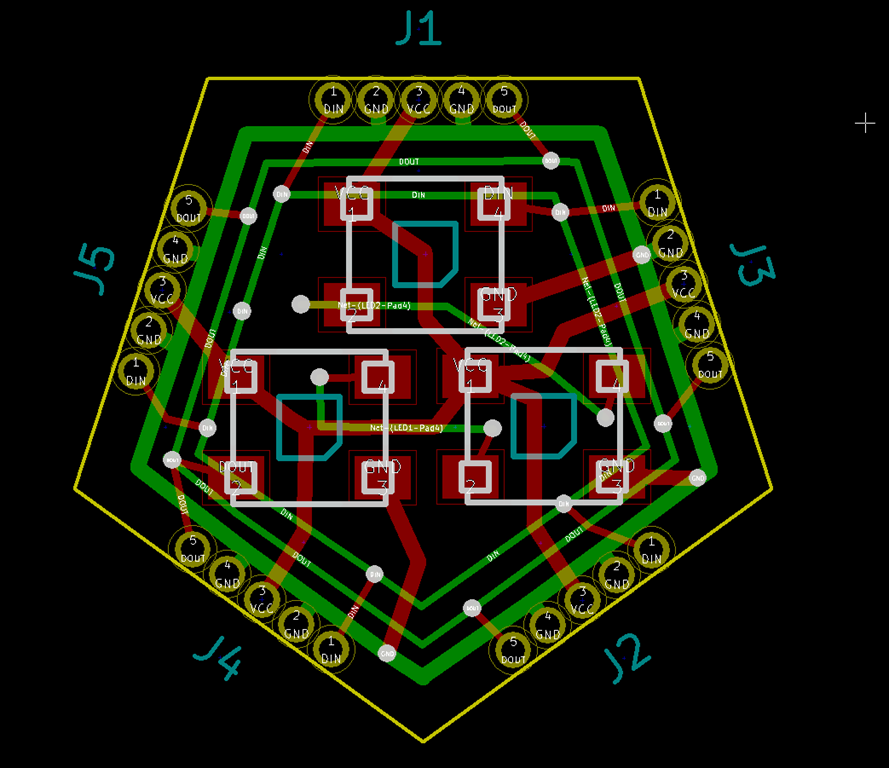
Obviously, the big different is the connectors; they are much larger, though the overall design is only a big bigger. I’ve used the extra space to pull the LEDs a bit farther apart because trying to hand-solder the LEDs in the first version was a difficult. And I added a little bypass jumper; if you solder a wire (or better, a 0805 zero-ohm resistor) across those pads, you can omit the bottom two LEDs and things will work fine.

If you read backwards, you might see that it says “Dodecahedral Light Engine” on the back, which is the new name for the boards.

A fully-populated DLE will features 33 LEDs, pull 2 amps @ 5V with everything on white, and put out quite a bit of light.

I need one more design review pass before I send this one out to have boards made.


Workshop finishing

My house is a little weird. The street is the high point of the property, and it slopes away toward the house and into the backyard, so I have a daylight basement in the back.

I also have a very rare commodity. I have a room underneath my two-car garage. The back half is full height, and then the front slopes up to driveway level.

The front half has some nice shelves that are used for storage, and the back has some old kitchen cabinets, yard tools, and some junk. The room is uninsulated and has no windows…

I have an office in the basement where my computer and my electronics workbench is, along with my 3d printer. That works great for those items, but when I bought a Glowforge, I didn’t want to have inside the house because of fumes. So, the logical place was to have it under the garage.

And since it’s winter, I’ve been freezing my butt off (in Washington state terms) whenever I need to cut things, and the Glowforge does have a lower temp limit.

So, it’s time to finish the space out. It’s going to get a window in the side wall, Roxul insulation in the walls, and CDX plywood on the walls. It *might* get roxul in the ceiling as well if it’s still too cold, and I’ve also considered a thermal blanket to separate the front section from the back if it turns out I spend a lot of time there.

Here’s the starting point:

IMG_9007

IMG_9008

IMG_9009

IMG_9010

IMG_9011


Chemistry nameplate

A somewhat belated present for my wife – belated because my Glowforge had to go back to the shop.

I wanted to do something chemistry-related for her. In the past I’ve bought her a few items like the MadeWithMolecules jewelry, but we all know that gifts that are handmade mean oh so much more.

So, I came up with a concept; a nameplate for her office with some sort of relevant compound on it, and ideally that compound would wrap over the top of her name.

The problem is that most organic compounds were either too complex or structurally inconvenient for the layout. I settled on dopamine, which looks like this:

Image result for dopamine

Which is fairly simple, except that I wanted to show all the atoms, so it really looks something like this:

Image result for dopamine model

I pulled out Visio and started playing around to see if I could get a two-dimensional representation that worked. And I did a bit of searching to find out atomic sizes and expected bond lengths, so that it could be accurate – which is a bit silly given that it pretends that atoms are round balls, but you get the idea.

Here’s what I ended up with:

image

Where:

  • Green = Oxygen (oxygen cylinders are green)
  • Blue = Hydrogen (because water is blue)
  • Grey = Carbon (it would be black, but the nameplate background is black)
  • Nitrogen = Yellow (because I like yellow and it looks good against black)

The atomic sizes and bond lengths are as close as I could get them. The bond angles are also mostly right, except for the two carbon/hydrogen bonds at the top; you have to pretend those are a 3-d projection.

I did a laser test engrave of that on some cheap plexiglass, and that worked okay, so I ordered up some 1/8” cast acrylic for the final version.

Unfortunately, the acrylic I ordered had plastic film protection rather than paper protection, and that plastic melted into the acrylic when I went to etch it, so the results sucked. About this time, my Glowforge went into permanent “too cold” state, so it had to go back, and then there were the holidays…

I eventually finished the prototype and gave it to my wife, and we agreed on two things. First, it was a little too small, and second, the saturated blue I used for the hydrogen atoms was too dark. So, here’s the remake of the production version, starting with the acrylic straight off the cutter:

IMG_9029

One of my challenges was figuring out how to paint it; a few tests showed that a brush was too big, and even a toothpick was too big; the bonds next to the tiny hydrogen atoms are *tiny*, and it’s important not to bleed paint from one area to another. I found some acrylic paint bottles, but they still had bit tips.

Finally, I found these:

image

These are syringes and tips that are sold as glue applicators. The tips are known as “Luer Lock” tips, and the twist right into the syringes. And this kit goes all the way to 25 gauge, which is *tiny*.

So, those showed up while waiting for the Glowforge, and then I had already purchased some acrylic paint from Michael’s:

image

If you are using the smallest tips, it’s pretty hard to suck paint up through them, so I used a big tip, pulled some paint into the syringe, and then switched to the smaller tip. It takes very small amounts of paint to do this; I have a lot more than I need here:

image

The technique is pretty simple; you put the tip into the corners and then carefully flow the paint into the corners to try to cover all of the walls in the paint, and after that you fill in the recess. I found that it made sense to work from different directions.

Partway through the name:

IMG_9031

Done with white (the bonds were a bitch, as I expected). This would look better but I didn’t clean the fine gauge tips well enough after the first version, so the ones I wanted to use were plugged.

IMG_9032

Done with paint. Those white spots are specular reflections from the track lights above my workbench

IMG_9033

Dry paint.

IMG_9034

And, finally, after the backing is removed:

IMG_9035

The coloring isn’t perfect; there are some spots where the black shows through, and in this light you can see the texture the laser cutter left. But overall, I think it’s pretty good, and it looks better in real life than in this shot.


Globes of Fire!

The parts for the new controller have started trickling in, but until they all show up I’m a stuck there, so I’ve been thinking in other areas.

In the olden days – pre LED – I had a number of the 50 or 100 light globes in my display:

See the source image

I liked them for their intense burst of light, but the ones I had gradually died, and I haven’t found a replacement.

So… I got thinking again about options. When I built my Animated Snowman, I used WS2182 leds on the faces of 3d-printed dodecahedra. It worked fine, but the hand-cabling was a pain:

IMG_8435[1]

Using the acrylic lamp globes worked great, however. They are cheap, easy to get, and fully waterproof. I just needed a better way to get the LEDs in place.

One of the nice things about dodecahedra is that the faces are all pentagons. I remember a hack-a-day article a couple of years ago when somebody built one by soldering pc boards together, so I decided to do a design of that what that might look like:

image

The concept is that any face can hook to any face. You wire up the ground and VCC connections on all faces to give rigidity to the dodecahedron, and then wire up the DIN and DOUT connections from face to face in whatever pattern makes sense.

This design gives me 12 LEDs (well probably 11, since the top or bottom one will be used for support) in the space of about an inch, so that would easily work in the small acrylic balls (6”, or 4” if I can get them).

Of course, why do one LED per face when you can do 3:

image

Same concept as before; hook up DIN from another face, it will chain through all three LEDs and then head out through DOUT.

This board is roughly an inch in size, so the resulting dodecahedron will be around 2” in size. That will give us 33 LEDs and live up to the title of the post, but it may be overkill, which is why I’m going two versions. I’ll drill a hole through the 12th face and use a threaded rod and nuts to mount the DLE (Dodecahedral Light Engine).

I need to do some design cleanup and then send off for a run of these to see how they work.