About 3 months ago, I wrote a post about an ESP-32 based remote control I’m building. Conceptually, what it does it allow you to press a button and hit a specific web endpoint.
Since the introduction, I wrote some code and got a prototype kindof working – the touch inputs on the ESP32 work fine, the deep sleep works okay, but I ran into a few problems.
First, the ESP32 can run on 3.0 volts but only kindof, and if you use two AAs their voltage drops pretty quickly to the point where the ESP stops working. Which means I needed a better power source, which means lithium based. I looked at primary (non-rechargeable) lithiums but they are also 3 volts (IIRC), I looked at lithium-ion, but 4.7 v is a really inconvenient voltage for ESPs; you need a regulator to get down there. Plus the 10850 cells are a bit big. Then I settled on LiFePo4 batteries, which very conveniently have a nominal voltage of 3.3 volts and are the same diameter (but shorter) than a AA, so they work well for packaging.
I bought a little battery monitoring board to protect the battery, but I’ve decided to skip it for this version. So, I think I’m set for batteries.
The second issues came up during my deep sleep testing. The ESP32 can get down to 10 uA in deep sleep, which looks great, *and* it supports “wait on touch” where it will turn on based on a touch input, which is also great. But…
The devkit boards that I have don’t support using it that way; even with the power led removed I think I was seeing about over 10mA when the ESP was in deep sleep. Not good enough. Some people have hacked their boards to remove some of the components, but traces are tiny and the board is dense, and I gave up after a few tries. I could use a module programmer like this which pulls the dev kit components onto the programmer and leaves just the raw board, but the problem there is I need a mounting solution that lets me program the same module every time.
What I really need is the dip part of the devkit board without any of the power supply or usb stuff and an adapter to hook that to the module programmer.
Since I haven’t figured that out, I went with the best deep sleep approach that I know, a rocker switch. I’m thinking that will get the power use all the way down to 0 uA.
The case
I have some plans for the version 2.0 case, but those require a fair amount of prework and new tools, and it’s nice enough that I could really use the remote *now*, so I went with with the easy approach – a laser cut box.
For touch points, I wanted some screw together pieces or screw studs, which I finally discovered were commonly known as “chicago screws”.
I wanted them in brass so that I can solder to them. The ones I got are 1/4” (6mm, actually) in length, which would be fine for my “real remote” design, but meant that I need to use 1/4” plywood for the face.
I did the design in Fusion 360. This design was not one of my better moments. I did the face in 1/4” but the sides on 1/8” so they would be thinner, but it turned out that I don’t have any 1/8” plywood left; what I have is 1/10”, so I had to redo the design. Then I measured the size of the studs very accurately with my calipers and then entered the shaft length (0.235”) instead of the shaft diameter (0.165”). And the power switch was too close to the corner so the top and side wouldn’t fit. Then I cut the top piece out of a piece of 1/8” scrap, so it was too big.
More trips back and forth than I had hoped, but it’s only computer and laser time plus a bit of wood, so it wasn’t that bad. Here’s the result:
Which is honestly pretty nice. The labels are engraved into the wood, and all it is missing is the power LED. The current plan is to glue the sides to the front and leave the back removable for access, but it’s not clear to me how that is going to work yet.
Video here:
Next up will be wiring up the front panel, assembling most of the box, and then hooking in the ESP and battery.
I’m not known for the cleanliness of my workspaces; my office desk is a mess right now, my garage workbench is a mess, as are my other workbenches.
But my electronics one is messy enough to be problematic, and the root problem is that there’s just too much stuff one the workbench; power supply, oscilloscope, toolbox, solder station, hot air rework station all take up a lot of space, and the work surface doesn’t have lot of depth, so I end up with a small clear workspace even without clutter.
A while back I was looking at my Rigol scope, and thought that I might have more room if I could mount it on the wall. And that obliquely led me to the current project.
I’ve been watching some woodworking on YouTube, and that led me to a series on french cleat walls. They are pretty popular for woodworking shops as they keep all of their tools handy. Looking at my garage space – where I do some woodworking-adjacent projects – I don’t have a lot of wall room for one of these, and most of projects I do occur elsewhere, so I wanted to keep my tools in their boxes. Not a great solution there.
But that triggered a thought about my electronics space; I don’t move my tools around and I could use the organization.
So I went looking in my garage and found that I had some leftover 12mm baltic birch plywood from another project, and I acquired some 2×3 pine for the cleats.
Making the cleat wall is pretty simple; you just cut your cleats wood at a 45 degree angle and then attach it to the plywood using a regular spacing. If you want details, here’s a video I did of the process:
I took the wall down to my workbench and attached it to the wall. Then it was time to start figuring out how to attach items to the wall; this is generally some sort of shelf or box with the mounting tabs that hook onto the cleat. First up was the oscilloscope, partly because it was big and partly because it was straightforward to design.
Oscilloscope Shelf
It’s simple enough that I could have just created a mock-up in cardboard and then used that to create the actual version, but I wanted to play a little, so I did a full CAD design. It was a pretty quick design in Fusion 360 and I’d show you a nice rendered version, but somehow it didn’t get saved along the way. Here’s what the side panel of the shelf looks like; the hole in the end is for the power cord at one end and the cooling fan at the other, and the left part hangs off the cleat:
Pro tip: The 1x stock you buy may not be exactly 3/4” thick; mine was 11/16” instead. So measure it first; for this shelf I had do sand down the back edge of the cleat.
The bottom shelf is just that, a rectangular piece of wood between the end pieces.
As a material I used some 1/4” baltic birch (probably 6mm actually), and I decided to use my Shaper Origin to make the shelf. It is held together with wood glue and some very thin wire pins shot in witn my pin nailer. Here’s the video if you want the details:
The result is nice and pretty, though I didn’t sweat trying to get things perfect; it’s not furniture:
Because of the way the cleats are designed, gravity pulls the mounting cleat both against the wall cleat and the wall plywood, and the back of the shelf presses against the second cleat. It’s surprisingly secure and yet very easy to move around.
About the time I was finishing this, I said to myself, “Self, that was fun and you made a lot of sawdust, but there’s nothing in that design that you couldn’t have done much quicker and easier with your laser cutter, so at this point I switched tools.
XBox 360 Power supply box
When I added a heated bed to my 3D printer, I bought an XBox 360 power supply to power it, and I found that they are wonderful for powering 12V loads; the ones I have provide up to 16 amps of power. So I bought a second one from Goodwill for $4.95 and have used it when I need a hefty supply for testing (like my WS2811 expander which I stress test with 3 50-watt 12v light bulbs). Cheap, compact, and lots of cheap power – what’s not to like.
Well, I don’t like that it’s cluttering up my workbench, so I’m going to build a box for it.
Here’s the CAD design, the laser-cut parts, and the final result. It’s cut out of 0.10” (2.5mm?) plywood that is strong and easy to cut on the laser (mine’s a GlowForge) and then glued together with wood glue.
I measured the power supply with my calipers and it ended up just on the tight side; the power supply slides in but barely. The big cutout for the close end is because there are air holes there.
The other end of the cable currently just has a set of speaker terminals that accept banana plugs and the enable wires soldered together so it’s always on. Sometimes in the future, that cables going to terminate in a power-supply box with an on off switch.
The xbox power supply hangs up high. And now I need a place to plug it in as the cord isn’t long enough to reach to the outlet under the workbench.
Power strip box
Another simple box, with the dimensions defined by the size of the power strip that I wanted to use. The design is quite simple with a bit of an assembly caveat; the box has both a top and a bottom so you have to assemble it around the power strip.
Resistor decade box
I built the decade box a few years ago based on this instructable. I do a fair bit of work with LEDs and I often find myself wanting to pick an LED value based either on measured current or brightness. I used to do that with a potentiometer, but it’s much easier to use a decade box.
The design here just has two end hangers; one end is attached using the output posts for the decade box, and the other one is just hot-glued on.
You might notice there are some smoke marks on the wood; if I wanted nice I would have masked them off but that was more work than I wanted for this.
Wire hanger
Just one more design for the first wave; I knew I would have wires running across the board and wanted a way to support them:
A simple three-piece design hold up a power cord. It’s tilted because of the weight of the cord is heavier on one side; I’ll probably do a version with a single hanger in the middle. Or I might cut some one-piece hangers out of 1/4” plywood.
Video tour
If you would prefer a video tour of the completed items, you can find it here:
Power supply hanger
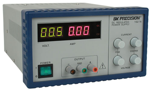
When looking at some of the small Chinese power supplies that are out there, I got a line on a nice surplus BK Precision 1627A on Ebay for $55 and ended up buying that instead. I have an older 4 voltage power supply (+12V, –12V, 5V, and adjustable) that I’ve used quite a bit, but it’s pretty rare that I need multiple voltages these days, I already have the hefty 12V, and I’m going to be adding some dedicated 5V supplies as well. I haven’t used +/- power supplies in a long time, so I think the old supply is going to get packed away for now.
To do a hanger for this looked a bit more challenging than my previous hangers because this is bigger and it weighs 16 pounds. I did the design and cut it out of 1/4” plywood:
The frames here are about 10” x 7” in size. They are cut out of 1/4” (probably 6mm, actually) and glued together.
Pro tip: Go back and look at the picture of the power supply picture above. If you look closely on the side and the talk, you will see some screws sticking out. If you measure precisely and cut to that precise measurement, the pretty holder you create will *not* fit over those screws, and you’ll need to remove the screws – and maybe the equipment feet – to get the frames to fit over the item (the power supply in this case).
Not only did I do that, but the first time I put the hanger on I had it on the wrong side, so I had to repeat it. But I did get to the final result:
Futures
One of my goals was to get my Fluke multimeter off my desk and up in the air, but there are some issues, the biggest one being that the digits are in shadow if the meter is vertical against the wall. I’ve had some designs that put it at the same angle the stand in the base does, some designs that let you modify the angle, and another idea that I might just add some white LEDs to the side so it could be vertical.
There will be a power supply station close at hand; I think it’s going to support 12V from the xbox supply, 5V both on banana plugs and on multiple USB plugs, and I might integrate one of the cheap chinese boost/buck supplies to give options.
Finally, there’s the right side of the bench, which has my soldering iron base and my cheap chinese hot-air rework station. I may end up with a cleat wall on that side I can get them up as well.
My skiing penguins project has been up and animating for a few weeks, and I thought I’d write down the process for others so that they can learn from what I did. And also so I can remember what I did and why. There are some other blog posts that talk about some of the specifics for the sequence controller I built.
First off, there’s a video here that shows the final result.
The my initial idea was to do something with LEDs and single frame animation; see some of the animations that were done at ZooLights at Pt. Defiance many years ago was what got me into this hobby. I had a big garage roof that was unutilized, and after some discussion with my wife we decided that skiing penguins was a good place to start.
CAD
I started looking around for online penguin designs to use as a starting point and found a couple. Then I started up Fusion 360 and created a new project.
I design (and sell) LED ornament kits, so I’m used to doing these designs. Here’s a video that shows the technique that I use to space the LEDs out evenly along an outline; that is what I used for all of the penguins. Here’s a in-process look at one of the designs:
and a final one:
The final designs were too big to cut in my laser cutter (glowforge), so I had to break them into two pieces. The puzzle-piece line gives me two individual pieces to cut that can easily be put together again.
The animation has 15 frames, which meant 29 individual pieces to cut.
Cutting
I figured out what sizes of plexiglass I needed and bought the plexiglass from my local TAP plastics; it was about $90 worth. I didn’t want to spend a lot of time splitting pieces on my table saw, so I defeated the door interlock on my Glowforge for the larger pieces:
You really shouldn’t do this if you don’t have laser safety glasses designed for your particular laser’s frequency. In this case, I wore my normal safety glasses and closed off as much of the opening as possible; I now have a nice set of dedicated laser safety glasses. Don’t do this unless you understand the risks.
Here’s all the cut pieces stacked up:
This is a penguin prototype:
This was actually constructed earlier; it was used to determine size, and we decided to go about 25% larger. Thankfully, Fusion made this fairly easy to do.
Here’s the first production frame:
You can see the glue residue along the joining line. At the left and right sides there are short connectors that overlap the joint and provide much needed stiffening; they are on both sides. The squares with holes are spacers; the penguins will mount to wood supports and the spacers hold the wood away from the wiring that will be on the back. Zoom in to see the fine details.
Here’s the pile of penguins all glued together and ready for LEDs.
First light on the first frame:
Green was planned for the body outline rather than the white in the prototype but I didn’t have enough green LEDs at the time. The LEDs are brightness matched to look similar to human eyesight though the blues look too bright to the camera. Only 13 more to go!
Here’s what the penguin looks like with the leds off:
Sorry about the messy and distracting background. For each section of LEDs, there are two sets of bare copper; one that is connected to 12V and one that is connected to ground. Leds are grouped based on their voltages; green and blue run in groups of 2 while reds run in groups of 4. At this point I realized that my ski poles had 9 leds which means that I had two groups of 4 and one individual LED, which was a pain. Each group has the appropriate resistor to set brightness. There are 70-odd LEDs in this frame, so figure something near to 200 solder joints.
Here’s a picture of the workbench mess:
That’s not that bad except there is more mess here:
and here:
To waterproof all the wiring, I took the penguins outside and hit them very heavily with clear acrylic spray. I’ll know how well that worked when I take them down:
Here’s a view of them drying. They have waterproof power connectors attached and have frame numbers marked on them.
And then they were each mounted on short pieces of 2×3 wood which would have been painted if I had time; maybe I’ll do that when I pull them down after they have dried out. You can see the wiring quite well in this shot, and we can see that it’s frame “J”, or the 10th frame.
The next step was to build the wiring harness. I did a diagram of the expected layout in Visio:
From that, I went out into my driveway, took a couple of tape measures, and laid out what I needed. The controller was planned to be under the roof where “K” is, so I would run wire to that point and then leave an extra 10’. I unfortunately don’t have any pictures of this process; I was racing the weather.
Basically, I would start at “A” in the diagram, leave a couple of feet of slack cable, run it up to D, across the top, and then down to K and leave 10’ at that end. Each cable gets an adhesive label with the circuit letter at each end, and those will later be covered with clear packing tape to waterproof them. Continue the process with each cable all the way through K. The cable is 22-gauge alarm cable; I have used twinlead in the past and I have to say that this cable was a huge upgrade in terms of ease of use, and at $31 for 500’ is was pretty cheap. I did calculations on the voltage drop and decided that it wasn’t too bad (about 7% IIRC).
Once I had all the cables, they got bunded together with wire ties at every branching location and then additional wire ties to make the harness easy to handle. I got it all done just as the rain came down for real, and headed inside. Each penguin location got the other half of the waterproof connector soldered on and then covered in heatshrink tubuing, and the controller ends got stripped to be connected to the controller. Here’s the final roof harness:
The penguins got installed on the roof with various arrangements of wood to support them and were plugged into the harness. I then spent a day or two figuring out how to do the penguins in front of the house; they are supported on 1/2” metal EMT tubing. I also created a separate harness for those penguins (one in the air, one crashed in the tree, and then a small one where the one in the tree lost his poles and skis) using the same process.
I finished building the controller:
Nearest to us is the ESP32 controller board that runs the animation software, and behind it are two custom 8-channel MOSFET switching boards. Attached to the back MOSFET board is a series of LEDs used for debugging.
The ESP runs custom software that drives the ESP32’s 16-channel PWM hardware. The ESP32 is ridiculously full-featured for the price. One of my goals for the project was to *not* have to pull the controllers out of their installed location to update the animation, so I created a really rudimentary web-based IDE and an animation language:
This is the current active view from the ESP running the penguins as I sit here and write. The left textbox shows the code and the right one shows errors if there are any. I wrote the animation outline and programmed it in, and then took my laptop to the garage and we’d watch the animation and I’d tweak it as necessary, it took us about 10 minutes to get what we wanted, and I would have spent more than that on a single iteration of “unplug the controller, take it downstairs, plug it in, modify the software, compile it, upload a new version, take it outside, plug it back in, and see if it worked”. That worked very well.
I’m calling the language “Dim”, because it’s good at dimming things and not very smart. In the code “DI” means drive a specific channel to a specific brightness over a specific cycle count (each cycle is about 10mS, so it runs at 100 Hz), and D lets you specify more than one operation to occur at once during the following “A” (animate) command. The language does have for loops but is desperately in need of functions/methods for this usage; I have those in a newer version.
Here’s a bit of code running on a second instance of the controller that flashes 5 of the ornaments I make in a random pattern:
Finally, here’s a daytime tour of the installation which shows the penguins mounted on the roof and in front of the garage and the controller board with terminal strips.
My first kit – the Dodecahedral Light Engine – has been selling about as well as I expected a very hard to construct project with limited usages to sell, which is not very well. I primarily did it because I was going to do them anyway for my decoration project and wanted a project I could learn on.
I’ve just started working on my second kit, which is going to be a lot easier to build, cheaper, and more widely useful.
One of my favorite displays is a “tree of lights”, which is a tree with custom LED ornaments on it:
The ornaments are made of small sheets of plexiglass with high-power LEDs inserted into the holes, wired up, and waterproofed.
They are really bright; note in the photo that all of the dim lights are normal brightness LEDs, and even at that level the ornaments overpower the camera sensor. They are bright enough that – and I am not making this up – they cast a shadow about 50 feet away when they were at full brightness, so I dialed them back a little in brightness.
These ones are driven directly from 120VAC as that is what the controller provides.
What I want from this project.
A fun, easy-to-assembly ornament
The ability to run off of 5V or 12V (*maybe* 120VAC with a big disclaimer that you shouldn’t really do it)
I’ve been spending some time doing a design in Fusion 360 for a laser-cuttable lantern, and I’ve discovered a few things. I’m recording them here to help others and to remind myself when I come back to this in a few months/years.
I started with a simple outline drawing of a tree that I wanted to use as the inset for the side panels:
I need to get that into Fusion in a way that works. Here’s what I came up with
From 2d to 3d
There are a couple of different approaches to doing this. If you have something that is simple, I recommend the “trace it yourself method”. In this, you insert the picture into Fusion as a Canvas (Insert->Attached Canvas), and then draw an outline in a sketch using it as a guide. I used splines and did a reindeer and rabbit outline pretty quickly, and then nice part is that manipulating the splines after that is simple and quick.
That was going to be a ton of work with the branches and I was both lazy and worried that it would be too complex to work well. So I took the alternate approach:
Load the image into Inkscape and save it as an SVG.
Use SVGtostl.com, upload the svg, and specify how thick you want it to be. You will be able to change this later though it’s a pain, so try to get close.
In Fusion, in a new design, choose Insert->Insert Mesh, and choose the file.
Switch from model mode to mesh mode.
In the browser tree, right-click on the mesh and choose “properties”. My trees end up with 13000 facets, which is about 3 times as many facets as I wanted.
Use the modify->remesh and modify->reduce options to get down the count that you want. You will probably have to experiment a bit to get it to work right. Start with Remesh, and preserve sharp edges and boundaries. You now have a mesh.
Switch from mesh mode to patch mode
Select the mesh in the browser
Modify->mesh to brep. This is changing from the mesh representation – which you can’t really modify in Fusion – to the brep representation, which you can. This may take a while. At this point, you have both a mesh and brep version of the object in the tree. Delete the mesh version as it’s just taking up memory.
If you look at the brep version, it has a ton of faces on it. This will slow things down, so it’s nice to clean up the faces. Modify->merge, choose “select chain”, and then click on one of the front faces. That should select all the faces.
Click “ok. That’s going to sit and spit for quite a while, but eventually it should finish and you should just see one common face. Or maybe Fusion will hang and you’ll have to restart it.
Convert the resulting body to a component, and save it.
Using the resulting design
The resulting design is very complex and will likely kill Fusion. It tried to use it to create panels for all four sides of the lantern, and that was a full failure; it would take a full 30 seconds to render.
What I ended up instead was doing the full design in Fusion without the complex branches. It looks something like this:
I designed one side of the lantern and then used pattern on path to duplicate it around 4 sides to make sure everything worked, and then used it to cut the top and bottom for the tab holes.
Then, I took the original side that I designed, converted it to a component, and did the compositing of the side and the branches in a design that only had those parts. That worked well from a performance standpoint and since all four sides are identical, I can just cut the single one four times.
To get this to work I had to move the components so they were okay left/right, use align to move the frame so the front is coplanar to the front of the branches, and then extrude a couple tools to cut off the branches where they were too wide for the frame.
Cutting on 2.7mm plywood (was supposed to be 3mm….) took about 5 minutes for each side, and a couple of minutes for the top and bottom.
Here’s a totally uncleaned/unsanded version. It would also look nicer if I taped the wood to protect it:
A somewhat belated present for my wife – belated because my Glowforge had to go back to the shop.
I wanted to do something chemistry-related for her. In the past I’ve bought her a few items like the MadeWithMolecules jewelry, but we all know that gifts that are handmade mean oh so much more.
So, I came up with a concept; a nameplate for her office with some sort of relevant compound on it, and ideally that compound would wrap over the top of her name.
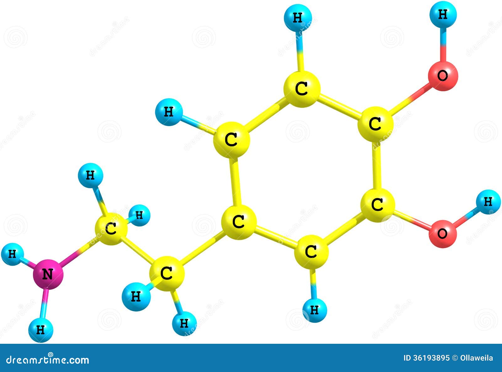
The problem is that most organic compounds were either too complex or structurally inconvenient for the layout. I settled on dopamine, which looks like this:
Which is fairly simple, except that I wanted to show all the atoms, so it really looks something like this:
I pulled out Visio and started playing around to see if I could get a two-dimensional representation that worked. And I did a bit of searching to find out atomic sizes and expected bond lengths, so that it could be accurate – which is a bit silly given that it pretends that atoms are round balls, but you get the idea.
Here’s what I ended up with:
Where:
Green = Oxygen (oxygen cylinders are green)
Blue = Hydrogen (because water is blue)
Grey = Carbon (it would be black, but the nameplate background is black)
Nitrogen = Yellow (because I like yellow and it looks good against black)
The atomic sizes and bond lengths are as close as I could get them. The bond angles are also mostly right, except for the two carbon/hydrogen bonds at the top; you have to pretend those are a 3-d projection.
I did a laser test engrave of that on some cheap plexiglass, and that worked okay, so I ordered up some 1/8” cast acrylic for the final version.
Unfortunately, the acrylic I ordered had plastic film protection rather than paper protection, and that plastic melted into the acrylic when I went to etch it, so the results sucked. About this time, my Glowforge went into permanent “too cold” state, so it had to go back, and then there were the holidays…
I eventually finished the prototype and gave it to my wife, and we agreed on two things. First, it was a little too small, and second, the saturated blue I used for the hydrogen atoms was too dark. So, here’s the remake of the production version, starting with the acrylic straight off the cutter:
One of my challenges was figuring out how to paint it; a few tests showed that a brush was too big, and even a toothpick was too big; the bonds next to the tiny hydrogen atoms are *tiny*, and it’s important not to bleed paint from one area to another. I found some acrylic paint bottles, but they still had bit tips.
Finally, I found these:
These are syringes and tips that are sold as glue applicators. The tips are known as “Luer Lock” tips, and the twist right into the syringes. And this kit goes all the way to 25 gauge, which is *tiny*.
So, those showed up while waiting for the Glowforge, and then I had already purchased some acrylic paint from Michael’s:
If you are using the smallest tips, it’s pretty hard to suck paint up through them, so I used a big tip, pulled some paint into the syringe, and then switched to the smaller tip. It takes very small amounts of paint to do this; I have a lot more than I need here:
The technique is pretty simple; you put the tip into the corners and then carefully flow the paint into the corners to try to cover all of the walls in the paint, and after that you fill in the recess. I found that it made sense to work from different directions.
Partway through the name:
Done with white (the bonds were a bitch, as I expected). This would look better but I didn’t clean the fine gauge tips well enough after the first version, so the ones I wanted to use were plugged.
Done with paint. Those white spots are specular reflections from the track lights above my workbench
Dry paint.
And, finally, after the backing is removed:
The coloring isn’t perfect; there are some spots where the black shows through, and in this light you can see the texture the laser cutter left. But overall, I think it’s pretty good, and it looks better in real life than in this shot.