
We’re in the process of doing some new landscaping in our back yard, and that involves a small fountain and some landscape lighting. Which of course brings up the question obvious question:
How are you going to control the fountain and the lighting?
Here are some initial requirements:
- There are three separate circuits of control; one for the fountain, one for the landscape lighting in the main beds, and one for the new general purpose lighting that will be mounted under the second floor eaves (the current lighting is big floodlights that provide really harsh illumination.
- The fountain is 120VAC; the landscape lighting is going to be low voltage.
- We need an easy way to turn each of them on and off.
- We would like to be able to have them function automatically on some sort of schedule.
- It would be nice if the schedule is tied into our light dark cycle automatically; I am far too lazy to remember to adjust them by hand.
The main controller will be based on a – no surprises here – an ESP8266 NodeMCU controller running a hacked-up variant of my animation software. The landscape lighting is going to be LED, which gives the following control requirements:
- Two AC circuits – one to control the fountain, and one to control the power supply for the landscape lights.
- Two DC circuits to control the two landscape light circuits independently.
The AC control will be done with a couple of solid state relays that I salvaged out of earlier holiday light projects. The DC control will be done with some nice power mosfets. I should be able to drive both directly from the controller.
All of this needs to fit in one half of an outlet box. I’m not sure the form factor; I’m thinking that I’m going to 3D print a box for the electronics, but how it fits into the duplex box is tbd. I *might* put override switches on the box so that if you want to you can just press a button to turn the lights on for an hour.
And you can take the underground conduit for the pump outlet and the wire for the landscape beds as “already implemented”.
Here are the parts that have already shown up:
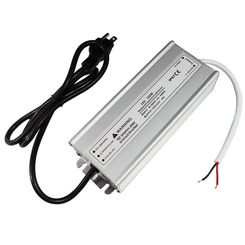
A 100 watt 12V DC power supply. It claims to be IP67 waterproof. The “6” means that it is “Dust Tight – No ingress of dust; complete protection against contact”. The “7” means “immersion up to 1m – ingress of water in harmful quantity shall not be possible when the enclosure is immersed in water under defined conditions of pressure and time (up to 1 m of submersion)”.
IP67 rating is impressively good. If it were true, I could drop this puppy into the fountain reservoir and it would keep running…
Alas, it is unlikely to be true; the ratings for much of the stuff out of China are hit and miss, with a bit more on the “miss” side of things. Which is why it’s going to be mounted up under the kitchen deck where water won’t be able to get to it.
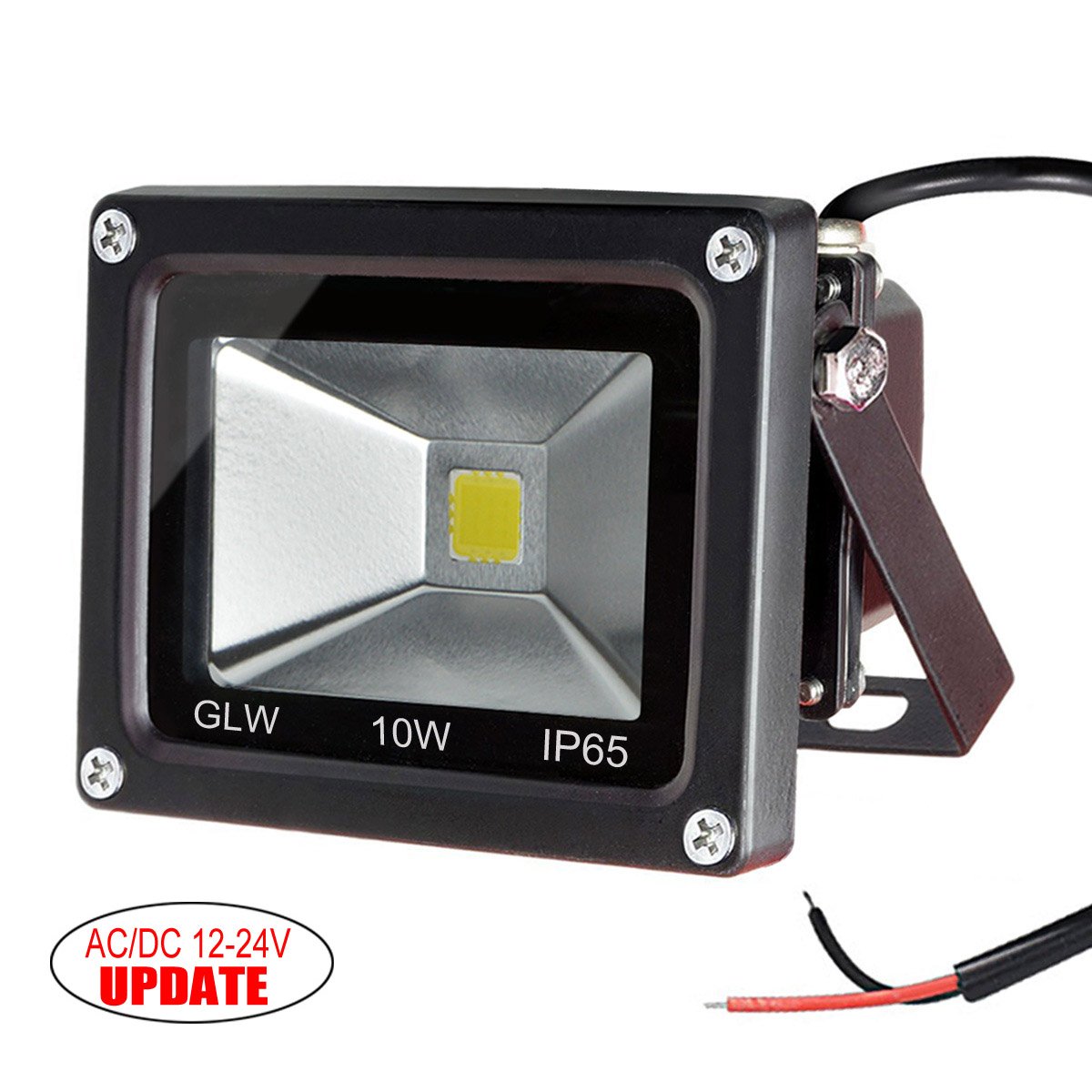
I should call these “ubiquitous 10 watt low voltage LED lights”. I have a bunch of these at my cabin, and they are pretty well made; nice heavy aluminum housings to get rid of the heat, decent mounting options. This go about 18’ up in the eaves to project a nice smooth light down on the yard. I bought 4 of them.
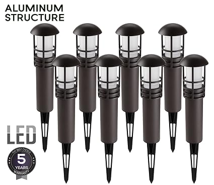
These are the pathway lights. I spent a lot of time trolling the chinese marketplace sites (aliexpress/alibaba etc.) looking for some decent lights that were cheap. What I found is that you can either buy high end lights that are $45 each, or you can buy part of an endless supply of really cheap and crappy solar lights, but nothing in between. So I settled for these from Amazon. The Amazon product is not linked because it has changed underneath to some other lights; suffice it to say that I bought 12 of these for about $13 each. These will be spaced out in the beds to make them look all pretty-like.
Astute readers will note that I’m using 36 watts for the pathway lights and 40 watts for the floods (or only 30 if I only put up three). That leaves me about 25 watts to spare. Some may go to accent lights on the north fence, and others might go for some lighting to help get to the hot tub. If I was smart, I would have gone bigger than 100 watts, but that can be replaced if necessary later on.
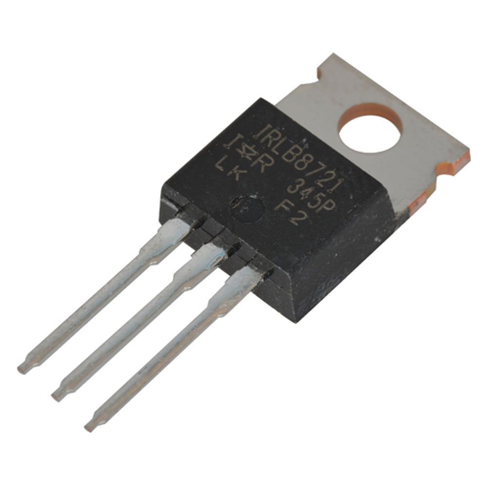
This is a nice little power MOSFET that will be switching the landscape light circuits. Why this MOSFET? Well, let’s look at the datasheet.
First off, MOSFETS are far nicer to use to switch loads than bipolar transistors. Bipolar transistors have significant downsides; you need quite a bit of current to switch big loads (the overhead lights will be about 3 amps) or you need darlington transistors, and because of the fixed collector/emitter voltage drop, you lose a lot of energy in the transistors, and they get hot.
This little MOSFET will happily switch 44 amps @ 10 volts and 100 degrees C, which is *way* more than it will ever see. It will switch 3 amps with 3 volts on the gate and 11 amps at 3.5 volts; the ESP runs at 3.3 volts so it will be enough to switch the current I need (if I needed big current, I’d need a bipolar driver in front to push the voltage higher). And – like most power MOSFETS – it has very low resistance between the drain and source (8.7 milliOhms with 10 volts on the gate). What that means is that it dissipates almost no energy as heat when on, and I can run it without a heat sink; it will at most get very slightly warm. And it also means I’ll send a full 12 volts out to the lights.
I guess I could also show the big 200’ roll of landscape cable. In the old world of incandescent lights, I would have needed to power these lights with a loop or maybe multiple wiring runs; in this world, the floods have their own power supplies so the voltage to them isn’t critical and the path lights don’t pull enough power to result in much voltage drop.
For the box connections, I’m thinking I will probably go with some molex connectors; that gives me a fairly safe way to hook up the AC to the power source and that way I can disconnect the whole module.
So, what do you think ?