
In our last installment, we were trying to decide whether to hand-wire the controller or to go with the PC board. The PC board won out handily since it only cost $13.30 for the standard 3 boards from OSHPark.
Here’s a picture of the board with populated with the 3 MOSFETs and 5 resistors. I did the solder paste application by hand since I only need to do one of these. Standard solder-paste since the MOSFETS may switch up to around 8 amps and therefore may get a bit warm.

And here’s a picture after the reflow. Reflow done in my Controleo 3 toaster oven reflow-er. Looks just fine.

One little comment: One problem I had during layout was how to connect the top pin of the MOSFETS to ground in a way that could flow enough current from the front to the back. My first design started with a number of vias, but I didn’t like it. Then I realize I had an easier solution; I just use a single through-hold pad and hand filled it with solder. It will carry far more current than I need.
Build
In my original concept all of this was going to fit inside of a double-gang electrical outlet box, but I realized that a) I’d rather mix as little low voltage and line voltage as possible and b) the box I used was only half-depth, so no room. Which argued to use a box and mount it to the house. Here’s the one I chose:

It’s a good size and has mounting bars. I don’t really need the gasket because I’ll be cutting holes for the wires. $11.60.
The next order of business was to figure out how to connect the big 12-gauge lighting wire to small connections on the board. I am lucky enough to have a good local Electronics store 15 minutes from my house (if you are in the Seattle area, Vetco is worth a trip), and that yielded a couple of terminal strips:
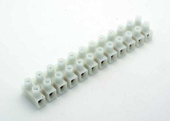
I think I bought two for $4.99 each, plus I bought some 18 gauge wire to go from the board to the strip (the big holes on the board can only support 18 gauge. Which led to this:

Those are all of the connections that take big wire, and the terminal strip color-coded with Sharpies.
Yes, I know I messed up the sequence; the 12V in at the lower right portion of the board really wanted to be there for each connection to the three 12V outputs. And it turns out that the wemos nodemcu layout I used was upside down, so the ESP-12 is hiding underneath the module rather than on top of it. There are female headers soldered to the board and male headers soldered to the nodemcu board. This allows me to easily remove it for reprogramming. Which was already required a time or two.
I used the same technique for the remaining controls I needed but they don’t map 1:1 to the board.

Here’s a few steps at once. I found an MDF cutoff and used that as the back of the board, and the screws that mount it also mount the terminal strips.
On the upper right terminal strip we have 120VAC coming into the box; that connects to a 5V power supply. There is a small 2AMP SSR that I had lying around that will switch on the 200 watt 12V power supply when it is needed. The “Pump on” output will connect to a similar SSR in the remote electrical box.
I did a full test of all the features, and they all worked. Well, except for the switching for the 12V power supply, which was broken by a refactoring I did in the software.
Umbrella lights
We have a shade umbrella with some chair under it, and one of the requirements was to have some light underneath it. I didn’t find any premade ones that I liked, so I bought 5 meters of 12V led strip and made my own. I made 8 strips that were 16” in length, attached wire, shrinkwrapped them, and then hooked them all together to a single supply. I only took one picture during construction:

But I did get this picture of them in operation:

Box installation
The box got installed on the wall and the various wires were hooked up. This is under my covered kitchen deck so there is no real chance of any water getting in.

The AC comes in from the far right; that is a 15’ extension cord that plugs into a GFI with an in-use cover; directly under that is the 12 volt 16.5 amp power supply which then feeds back into the 12V input for the board. The red/white wire carries a 5V signal to the SSR in the electrical box that controls the fountain. The three main loads are hooked in along the bottom.
There are two things missing in this picture; the 12V line that used to run the stair lights is not hooked in, and the stair lights are not connected into one of the existing lines. It turns out the transformer for the stair lights does not put out 12V with no load; it puts out 17.3V. I did a conservative design on the board that would support 15V without damaging the ESP, but 17.3V was too much. I therefore built a small in-line voltage divider and used that to connect the stair lights in.
As of now, everything works fine delta one bug that I am chasing down.
I’ll write up a post about the software next.
So, what do you think ?