I’ve been working on a little ESP32 expansion board/shield for an LED project I’ve been working on. One of the nice things about the ESP32 is that it has a peripheral known as “LED control” that provides 16 independent channels of PWM for controlling LED brightness, and my project uses that capability.
One of my projects is going to require all 16 channels, so I wanted to do a board that would support 16 channels, but I also wanted a version of the board that would only support 8 channels. I started with the 8 channel board and figured out a way to build a single board that would support 8 channels and also function as an expansion board to add the other 8 channels. I thought the approach was interesting enough to share it here…
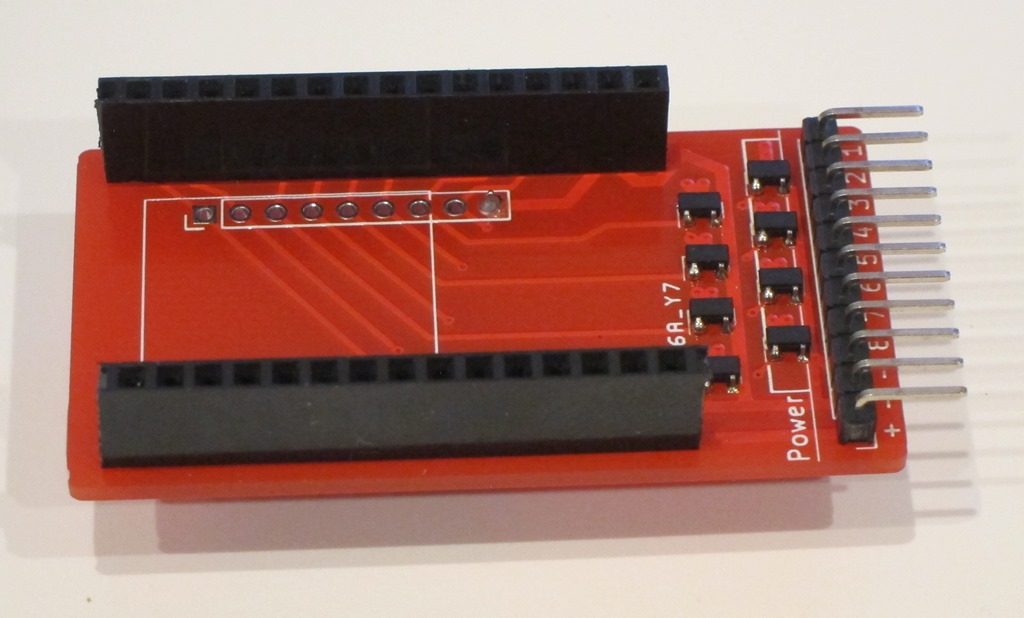
Let’s start with a picture of the board:
I’m using the 20-pin development board, and it turns out that of the 16 channels supported by the LED control peripheral, half of them are on each set of pins. I started doing an 8-channel version of the controller; you can see the primary pins on the right side of the board that come into the center of the board and then head down into the MOSFET region of the board. That design was fairly simple to do.
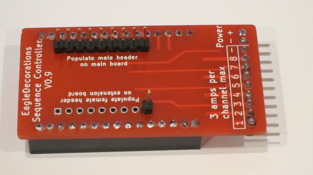
Then I needed a way to do something with the 8 channels on the other set of pins. At that point, I realized that if I could use the same board to get the other 8 channels if I flipped the board over:
On the primary board, the pins for channels 9-16 on the left side of the board are connected to a header. The ESP32 will be connected to headers on the top side of the primary board, and then we will add a header to the primary board expansion pins – pins 9-16 – on the underside of the primary board.
We will then take a second board and flip it upside down. That puts the header pins that are connected to the MOSFETs on the left side of layout directly under the header on the primary board connected to the expansion pins, so we can just put a complementary header on the expansion board and just stack them together.
Here’s what it looks like in the real world. This is the primary board with headers for the ESP-32 on the left and MOSFETs on the right. That is set up for 8-channel mode.
To enable 16-channel mode, we flip this board over and add some headers. The top header connects to pins 9-16 from the ESP32, and then there’s a single pin on the bottom which connects to ground (if I do a future version I’ll add an extra pin on the left) to provide a bit more support. 
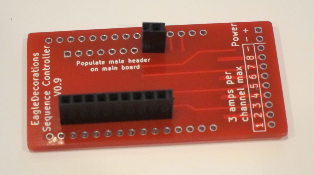
We then take a second board and set it up as an expansion board by adding the complementary headers to it.
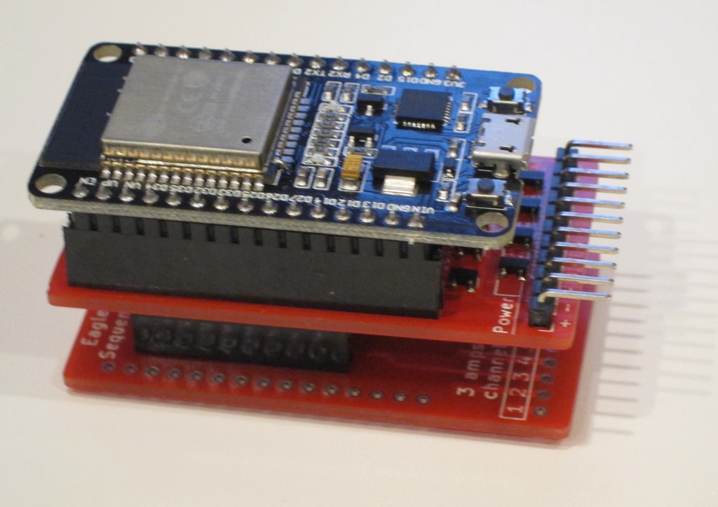
We can then finally stack the expansion board on the back of the primary board and add the ESP32:
That gives us 16 outputs.
Here’s a short video demo of the controller:
And a second video that show my first project using it:


What chip does it use to run the PWMs? That seems to be a crucial piece of missing information. For my application I’d need to control PWM frequency, phase, and duty cycle ideally per channel. Some PWM expanders can do this, others cannot.
The ESP-32 has a built-in subsystem for driving LEDs that handles 16 channels in parallel. It supports per-channel PWM.
See chapter 14 here for more info: https://www.espressif.com/sites/default/files/documentation/esp32_technical_reference_manual_en.pdf