Browsing posts in: Electronics

Write and debug your Arduino programs on your desktop part 3: Fading

In the first post I said we would be doing a Larson scanner, and all we’ve done so far is make a light that goes back and forth in different colors. That is cool and all, but what about the FADING!

In standard Larson scanner, this is pretty easily done; you just need a way to go backwards for <n> steps and then you just write the bright color at the current spot and then dim it as you go backwards. With the color wheel, however, you would need to keep track of what the colors of the previous spots were and dim that color.

Seems like a lot of work to me.

Instead, we’re going to be building something that I think is a little cooler – a fading LED strip. Set a point to a specific color, and over <N> steps, it will automatically fade to black.

Hmm. It sounds like what we need is some code that can blend from a color to black. We already have a class that can do that – the ColorBlend class. We can just leverage that to do what we want. Here’s a test:

static void TestSingleFade()
{
     FadingLedStrip fadingLedStrip(4);
     LedStrip ledStrip;


    LedColor ledColor;


    fadingLedStrip.setColor(1, 255, 0, 0);


    fadingLedStrip.show(ledStrip);
     ledColor = ledStrip.getColor(1);
     Assert::AreEqual(255, ledColor.Red);


    fadingLedStrip.show(ledStrip);
     ledColor = ledStrip.getColor(1);
     Assert::AreEqual(191, ledColor.Red);


    fadingLedStrip.show(ledStrip);
     ledColor = ledStrip.getColor(1);
     Assert::AreEqual(127, ledColor.Red);


    fadingLedStrip.show(ledStrip);
     ledColor = ledStrip.getColor(1);
     Assert::AreEqual(63, ledColor.Red);


    fadingLedStrip.show(ledStrip);
     ledColor = ledStrip.getColor(1);
     Assert::AreEqual(0, ledColor.Red);
}

We set a color and then each time we call show(), it dims the color down. In this case, the dim count is set to 4, so it will take 4 more steps to dim all the way down.

The code for FadingLedStrip is here:

class FadingLedStrip
{
     int _steps;


    ColorBlender _blenders[15];


public:
     FadingLedStrip(int steps)
     {
         _steps = steps;
     }


    void setColor(int ledNumber, int red, int green, int blue)
     {
         _blenders[ledNumber].blendToColor(LedColor(red, green, blue), 0);
         _blenders[ledNumber].blendToColor(LedColor(0, 0, 0), _steps);
     }


    void show(LedStrip& ledStrip)
     {
         for (int i = 0; i < 15; i++)
         {
             LedColor ledColor = _blenders[i].getCurrentColor();
             ledStrip.setColor(i, ledColor.Red, ledColor.Green, ledColor.Blue);
             _blenders[i].step();
         }


        ledStrip.show();
     }
};

It keeps an array of ColorBlenders – one per LED. When we set a color, we tell the blender to immediately switch to that color, and we also tell it to blend to black of the specified number of steps.

The show() method then walks through all of the blenders and copies the color of each blender to the real strip and tells the blender to step.

Here’s a video of the final result:


Larson Scanner from Eric Gunnerson on Vimeo.


Write and debug your Arduino programs on your desktop part 2: Automated Testing

Read the previous post before you read this one.

In the previous post, I showed how to use hand-verification – and perhaps a debugger – to get your code working. That works well in many cases, but sometimes you have code that you think is going to evolve over time or code where it is tedious to do the hand verification.

The alternate is to automate that verification, using what is commonly known as “Unit Tests”.

Blending colors

The current implementation only uses red, green, and blue. It would be much nicer if it could smoothly change between colors. I’m going to be building a way to blend from the current color to a new color in a specified number of steps.

I’m going to do this implementation in small steps, using a technique where I write the test before I write the code. To start, we need to switch to a new color immediately when the user chooses zero steps.

Here’s my test code:

static void TestZeroSteps()
{
     ColorBlender colorBlender;


    colorBlender.blendToColor(LedColor(255, 0, 255), 0);


    LedColor color = colorBlender.getCurrentColor();
     Assert::AreEqual(255, color.Red);
     Assert::AreEqual(  0, color.Green);
     Assert::AreEqual(255, color.Blue);
}

The test blends to (255, 0, 255) – purple – in zero steps, so the next time getCurrentColor() is called, it should return that color.

The Assert::AreEqual() statements are verifying that the values we get back are the ones we expect; if they are not, a message will be written out to the console.

This test code lives in the ColorBlenderTest.h file.

The code for ColorBlender lives in the arduino project, and looks like this:

class ColorBlender
{
     LedColor _targetColor;


    public:


    LedColor getCurrentColor()
     {
         return LedColor(_targetColor.Red, _targetColor.Green, _targetColor.Blue);
     }


    void blendToColor(LedColor targetColor, int steps)
     {
         _targetColor = targetColor;
     }
};

When run, that produces no errors. In the next test, we’ll do the blend in one step. Here’s a new test:

static void TestOneStep()
{
     ColorBlender colorBlender;


    colorBlender.blendToColor(LedColor(255, 0, 255), 1);


    LedColor color = colorBlender.getCurrentColor();
     Assert::AreEqual(0, color.Red);
     Assert::AreEqual(0, color.Green);
     Assert::AreEqual(0, color.Blue);


    colorBlender.step();


    color = colorBlender.getCurrentColor();
     Assert::AreEqual(255, color.Red);
     Assert::AreEqual(0, color.Green);
     Assert::AreEqual(255, color.Blue);
}

The initial color should be black, and then after calling step(), it should move to the new color. When this is run, we get the following:

Assert: expected 0 got 255

We get those errors because there is no implementation to make the test work. This code will make it work:

class ColorBlender
{
     LedColor _currentColor;
     LedColor _targetColor;


    public:


    LedColor getCurrentColor()
     {
         return LedColor(_currentColor.Red, _currentColor.Green, _currentColor.Blue);
     }


    void blendToColor(LedColor targetColor, int steps)
     {
         _targetColor = targetColor;


        if (steps == 0)
         {
             _currentColor = _targetColor;
         }
     }


    void step()
     {
         _currentColor = _targetColor;
     }
};

and now, onto two steps. Here’s the test:

static void TestTwoSteps()
{
     ColorBlender colorBlender;


    colorBlender.blendToColor(LedColor(255, 0, 255), 2);


    LedColor color = colorBlender.getCurrentColor();
     Assert::AreEqual(0, color.Red);
     Assert::AreEqual(0, color.Green);
     Assert::AreEqual(0, color.Blue);


    colorBlender.step();


    color = colorBlender.getCurrentColor();
     Assert::AreEqual(127, color.Red);
     Assert::AreEqual(0, color.Green);
     Assert::AreEqual(127, color.Blue);


    colorBlender.step();


    color = colorBlender.getCurrentColor();
     Assert::AreEqual(255, color.Red);
     Assert::AreEqual(0, color.Green);
     Assert::AreEqual(255, color.Blue);
}

and the updated code:

class ColorBlender
{
     float _red = 0.0F;
     float _green = 0.0F;
     float _blue = 0.0F;
     float _redDelta = 0.0F;
     float _greenDelta = 0.0F;
     float _blueDelta = 0.0F;


    LedColor _targetColor;


    public:


    LedColor getCurrentColor()
     {
         return LedColor((int) _red, (int)_green, (int)_blue);
     }


    void blendToColor(LedColor targetColor, int steps)
     {
         _targetColor = targetColor;


        if (steps == 0)
         {
             _red = _targetColor.Red;
             _green = _targetColor.Green;
             _blue = _targetColor.Blue;
         }
         else
         {
             _redDelta = (_targetColor.Red – _red) / steps;
             _greenDelta = (_targetColor.Green – _green) / steps;
             _blueDelta = (_targetColor.Blue – _blue) / steps;
         }
     }


    void step()
     {
         _red = _red + _redDelta;
         _green = _green + _greenDelta;
         _blue = _blue + _blueDelta;
     }
};

That works. One more test to add; we should stop blending even if we go beyond the specified number of steps. Here’s a test for it:

static void TestThreeStepsAndHold()
{
     ColorBlender colorBlender;


    colorBlender.blendToColor(LedColor(10, 0, 0), 3);


    Assert::AreEqual(0, colorBlender.getCurrentColor().Red);
     colorBlender.step();


    Assert::AreEqual(3, colorBlender.getCurrentColor().Red);
     colorBlender.step();


    Assert::AreEqual(6, colorBlender.getCurrentColor().Red);
     colorBlender.step();


    Assert::AreEqual(10, colorBlender.getCurrentColor().Red);
     colorBlender.step();


    Assert::AreEqual(10, colorBlender.getCurrentColor().Red);
}

That fails on the last assert, as it keeps adding and gives us 13. I added some code and ended up with this:

class ColorBlender
{
     float _red = 0.0F;
     float _green = 0.0F;
     float _blue = 0.0F;
     float _redDelta = 0.0F;
     float _greenDelta = 0.0F;
     float _blueDelta = 0.0F;


    LedColor _targetColor;
     int _steps;


    public:


    LedColor getCurrentColor()
     {
         return LedColor((int) _red, (int)_green, (int)_blue);
     }


    void blendToColor(LedColor targetColor, int steps)
     {
         _steps = steps;
         _targetColor = targetColor;


        if (steps == 0)
         {
             _red = _targetColor.Red;
             _green = _targetColor.Green;
             _blue = _targetColor.Blue;
         }
         else
         {
             _redDelta = (_targetColor.Red – _red) / steps;
             _greenDelta = (_targetColor.Green – _green) / steps;
             _blueDelta = (_targetColor.Blue – _blue) / steps;
         }
     }


    void step()
     {
         if (_steps != 0)
         {
             _red = _red + _redDelta;
             _green = _green + _greenDelta;
             _blue = _blue + _blueDelta;
             _steps–;
         }
     }
};

All of that was written without and tested without any interaction with my microcontroller.

Doing something nice with the blender…

The blender by itself isn’t that useful; we need something to drive it through different colors. Here’s ColorWheel.h:

class ColorWheel
{
     int _stepCount;
     ColorBlender _colorBlender;
     LedColor _colors[6] = {
         LedColor(255, 0, 0),
         LedColor(255, 255, 0),
         LedColor(0, 255, 0),
         LedColor(0, 255, 255),
         LedColor(0, 0, 255),
         LedColor(255, 0, 255) };
     int _colorIndex = 0;


    public:
         ColorWheel(int stepCount)
         {
             _stepCount = stepCount;
             _colorBlender.blendToColor(_colors[_colorIndex], 1);
         }


        LedColor getNextColor()
         {
             _colorBlender.step();
             LedColor ledColor = _colorBlender.getCurrentColor();
             if (_colorBlender.isDone())
             {
                 _colorIndex = (_colorIndex + 1) % 6;
                 _colorBlender.blendToColor(_colors[_colorIndex], _stepCount);
             }


            return ledColor;
         }
};

It uses a ColorBlender, and whenever a color blender is done – which is checked through a new “isDone()” method – it will add a blend to the next color in the sequence. So it continuously cycles through the 6 main colors (Red, yellow, green, cyan, blue, purple).

It has tests:

#pragma once
#include “..\Arduino\Larson\src\ColorWheel.h”


class ColorWheelTest
{
     static void TestSingleStepWheel()
     {
         ColorWheel colorWheel(1);
        
         LedColor ledColor = colorWheel.getNextColor();
         Assert::AreEqual(255, ledColor.Red);
         Assert::AreEqual(  0, ledColor.Green);
         Assert::AreEqual(  0, ledColor.Blue);


        ledColor = colorWheel.getNextColor();
         Assert::AreEqual(255, ledColor.Red);
         Assert::AreEqual(255, ledColor.Green);
         Assert::AreEqual(  0, ledColor.Blue);


        ledColor = colorWheel.getNextColor();
         Assert::AreEqual(  0, ledColor.Red);
         Assert::AreEqual(255, ledColor.Green);
         Assert::AreEqual(  0, ledColor.Blue);


        ledColor = colorWheel.getNextColor();
         Assert::AreEqual(  0, ledColor.Red);
         Assert::AreEqual(255, ledColor.Green);
         Assert::AreEqual(255, ledColor.Blue);


        ledColor = colorWheel.getNextColor();
         Assert::AreEqual(  0, ledColor.Red);
         Assert::AreEqual(  0, ledColor.Green);
         Assert::AreEqual(255, ledColor.Blue);


        ledColor = colorWheel.getNextColor();
         Assert::AreEqual(255, ledColor.Red);
         Assert::AreEqual(  0, ledColor.Green);
         Assert::AreEqual(255, ledColor.Blue);


        ledColor = colorWheel.getNextColor();
         Assert::AreEqual(255, ledColor.Red);
         Assert::AreEqual(  0, ledColor.Green);
         Assert::AreEqual(  0, ledColor.Blue);
     }


    static void TestFourStepWheel()
     {
         ColorWheel colorWheel(4);


        LedColor ledColor = colorWheel.getNextColor();
         Assert::AreEqual(255, ledColor.Red);
         Assert::AreEqual(0, ledColor.Green);
         Assert::AreEqual(0, ledColor.Blue);


        ledColor = colorWheel.getNextColor();
         Assert::AreEqual(255, ledColor.Red);
         Assert::AreEqual(63, ledColor.Green);
         Assert::AreEqual(0, ledColor.Blue);


        ledColor = colorWheel.getNextColor();
         Assert::AreEqual(255, ledColor.Red);
         Assert::AreEqual(127, ledColor.Green);
         Assert::AreEqual(0, ledColor.Blue);


        ledColor = colorWheel.getNextColor();
         Assert::AreEqual(255, ledColor.Red);
         Assert::AreEqual(191, ledColor.Green);
         Assert::AreEqual(0, ledColor.Blue);


        ledColor = colorWheel.getNextColor();
         Assert::AreEqual(255, ledColor.Red);
         Assert::AreEqual(255, ledColor.Green);
         Assert::AreEqual(0, ledColor.Blue);


        ledColor = colorWheel.getNextColor();
         Assert::AreEqual(191, ledColor.Red);
         Assert::AreEqual(255, ledColor.Green);
         Assert::AreEqual(0, ledColor.Blue);
     }


public:
     static void RunTests()
     {
         TestSingleStepWheel();
         TestFourStepWheel();
     }
};

and that makes the Animater simpler. Here’s the running code:

#define NUM_LEDS 15


class Animater
{
     int _last = 0;
     int _current = 0;
     int _increment = 1;


    int _color = 0;
     ColorWheel _colorWheel;


    public:


    Animater() : _colorWheel(20) {}


    void doAnimationStep(LedStrip &ledStrip)
     {
         ledStrip.setColor(_last, 0, 0, 0);
         LedColor ledColor = _colorWheel.getNextColor();


        ledStrip.setColor(_current, ledColor.Red, ledColor.Green, ledColor.Blue);
         ledStrip.show();


        _last = _current;
         _current = _current + _increment;


        if (_current == 0 || _current == NUM_LEDS – 1)
         {
             _increment = -_increment;
         }
     }
};


Write and debug your Arduino programs on your desktop

Working on projects with an Arduino – or with other microcontrollers – can be a lot of fun. It can also be a frustrating experience; you write some code and then you need to wait for it to be compiled, packaged up, downloaded to your microcontroller, and then run. And when it doesn’t work, it can be difficult to figure out why it isn’t working; generally, the best you can do look at the output from Serial.println() or look at the signals on an oscilloscope, if you own one.

As a (now former) professional developer, I was sure that there was a better way, and after some experimentation I came up with the method described in these posts.

Basically, the approach is pretty simple. We are going to structure our software so that there are two discrete parts; a first part that is directly dependent on the microprocessor and libraries and a second part that is generic. The second part will contain the bulk of the code that we will be writing.

And then, we are going to use a generic C++ environment to run the code from the second part and verify that it works. Once we have it working in that environment, we can then move over to the arduino environment and test it on the real hardware.

In addition to making it easier to write and verify code, this will also break our code into parts and make it simpler to understand.

Tools

We will be using two different development environments. For our Arduino code, we need an Arduino environment – what I would call an “IDE”. I’m going to be using Visual Studio Code with the Platform IO package, but you can use the Arduino IDE if you’d rather. Both of those are free.

We will also need a desktop/laptop environment that can run C++ code. There are several good options here; I’m going to stay true to my roots and use Visual Studio Community with C++ support installed (also free) for that development, but you can use whatever environment you would like.

The project

A quick look at my blog will indicate that I am quite devoted to LEDs, so that’s what we’re going to build. Specifically a Larson Scanner:

Or at least something like that; I’m not sure we’re going to get to the dimming trail part. If you want to follow along, you’ll need a microcontroller that can run the FastLed library (I’m going to use an ESP8266 board), and a strip of WS2812/Neopixel LEDs. There’s a nice intro to using FastLED in their wiki here, and I suggest getting something working in your environment using their directions before trying to follow along.

I’ll add a note here that if you are using the ESP8266, Makuna’s NeoPixelBus is a better choice than FastLed as it has hardware support, but FastLed is more popular so that’s why I’m using it here.

First Version

All of the code lives in the LarsonScanner repository. I will try to keep my commits small and informative so you can see what the changes are.

I started by writing a quick and minimal version of the code. It looks like this:

#include <Arduino.h>
#define FASTLED_ESP8266_NODEMCU_PIN_ORDER
#include <fastled.h>


#define NUM_LEDS 15
#define DATA_PIN 3


CRGB leds[NUM_LEDS];


void setup() {
   FastLED.addLeds<NEOPIXEL, DATA_PIN>(leds, NUM_LEDS);
}


int last = 0;
int current = 0;
int increment = 1;


void loop() {
  leds[last] = CRGB::Black;


  leds[current] = CRGB::Red;
   FastLED.show();
   last = current;
   current = current + increment;


  if (current == 0 || current == NUM_LEDS – 1)
   {
     increment = -increment;
   }


  delay(30);
}

Most of this is boilerplate FastLED code. The code itself is simple; it has three variables:

  • current defines the next LED that we need to turn on
  • last defines the LED that is currently on that we will need to turn off
  • increment defines the direction we are moving with the animation

The loop code sets the previous LED off and turns the new one on, and then increments to move to the next LED. If that puts us at the ends of the strip – either LED 0 or LED NUM_LEDS-1 – then that tells us we need to start going the other direction and we negate increment to do that.

Running this code on the desktop

Our goal is to be able to run the code that we wrote – the code to do the animation – on the desktop. But we can’t do this because that code calls the FastLED library, and there’s no FastLED library on the desktop. What we will need to do is provide a way for our animation code to *use* the FastLED code indirectly rather than referring to it directly.

In software development terms, we’re doing what is called “encapsulation”; taking all of the code related to a specific operation and separating it from the rest of our code.

We will take all the FastLED code and move it into a separate class. It looks like this:

#define FASTLED_ESP8266_NODEMCU_PIN_ORDER
#include <fastled.h>


#define NUM_LEDS 15
#define DATA_PIN 3


class LedStrip
{
     CRGB _leds[NUM_LEDS];


    public:
     void setup()
    {
         FastLED.addLeds<NEOPIXEL, DATA_PIN>(_leds, NUM_LEDS);
     }


    void setColor(int ledIndex, int red, int green, int blue)
     {
         _leds[ledIndex] = CRGB(red, green, blue);
     }


    void show()
     {
         FastLED.show();
     }
};

This new class now keeps track of the details of dealing with FastLED. Note that the “leds” array has been renamed “_leds”; that is a naming convention to make it easier to know that it belongs to this class.

Our main code now looks like this:

#include <Arduino.h>
#include <LedStrip.h>


LedStrip ledStrip;


void setup() {
   ledStrip.setup();
}


int last = 0;
int current = 0;
int increment = 1;


void loop() {


  ledStrip.setColor(last, 0, 0, 0);
   ledStrip.setColor(current, 255, 0, 0);
   ledStrip.show();


  last = current;
   current = current + increment;


  if (current == 0 || current == NUM_LEDS – 1)
   {
     increment = -increment;
   }


  delay(30);
}

Better. There are no FastLED details in here, but there are still arduino details that would get in the way of using it from the desktop. Just as we took all the FastLED details and put them in a class, we will now put all of the animation details into a separate class. It looks like this:

#define NUM_LEDS 15


class Animater
{
     int _last = 0;
     int _current = 0;
     int _increment = 1;


    public:


    void doAnimationStep(LedStrip &ledStrip)
     {
         ledStrip.setColor(_last, 0, 0, 0);
         ledStrip.setColor(_current, 255, 0, 0);
         ledStrip.show();


        _last = _current;
         _current = _current + _increment;


        if (_current == 0 || _current == NUM_LEDS – 1)
         {
             _increment = -_increment;
         }
     }
};

That puts all the code in a method named doAnimationStep; we pass in an LedStrip, and it does whatever it needs to do.

Our main program code gets even simpler:

#include <Arduino.h>
#include <LedStrip.h>
#include <Animater.h>


LedStrip ledStrip;
Animater animater;


void setup() {
   ledStrip.setup();
}


void loop() {
   animater.doAnimationStep(ledStrip);
   delay(30);
}

This demonstrates quite well why encapsulation is a good thing; instead of having one main program with different things going on, we have three sections of code; the code that only deals with FastLED operations, the code that deals with the animation, and then a very simple bit of code that hooks them together. If your arduino code is getting complicated and hard to understand, using encapsulation will help immensely.

The desktop version

We are now ready to run our animation code. I’ve created a Visual Studio C++ project named “ConsoleTest” next to the arduino project. My goal is to run the code in Animater.h in this environment, and to do that, I’m going to need a different implementation of LedStrip.h. Here’s what I create in the ConsoleTest project:

class LedStrip
{
public:
     void setColor(int ledNumber, int red, int green, int blue)
     {
         printf(“LED %d: (%d, %d, %d) \n”, ledNumber, red, green, blue);
     }


    void show()
     {
         printf(“Show: \n”);
     }
};

Instead of talking to an LEDStrip, it just writes out the information it is called with to the console.

The ConsoleTest.cpp file in this project looks like this:

#include “stdafx.h”
#include “LedStrip.h”
#include “..\Arduino\Larson\src\Animater.h”


int main()
{
     LedStrip ledStrip;
     Animater animater;


    for (int i = 0; i < 30; i++)
     {
         animater.doAnimationStep(ledStrip);
     }


    return 0;
}

It includes the printing version of LedStrip in the test project, but it then includes Animater.h from the arduino project. The main() function then calls the animation code the same way the arduino code would call it. It generates the following output:

LED 0: (0, 0, 0)
LED 0: (255, 0, 0)
Show:
LED 0: (0, 0, 0)
LED 1: (255, 0, 0)
Show:
LED 1: (0, 0, 0)
LED 2: (255, 0, 0)
Show:
LED 2: (0, 0, 0)
LED 3: (255, 0, 0)
Show:
LED 3: (0, 0, 0)
LED 4: (255, 0, 0)
Show:
LED 4: (0, 0, 0)
LED 5: (255, 0, 0)
Show:
LED 5: (0, 0, 0)
LED 6: (255, 0, 0)
Show:
LED 6: (0, 0, 0)
LED 7: (255, 0, 0)
Show:
LED 7: (0, 0, 0)
LED 8: (255, 0, 0)
Show:
LED 8: (0, 0, 0)
LED 9: (255, 0, 0)
Show:

We are now able to see the calls the animation code would make to the FastLED library when it runs on the arduino and see if it is behaving as expected.

Digression for experienced developers

If you aren’t an experienced developer, you can safely ignore this section.

This technique – which I call “abstraction by include file” – likely looks a little weird. The “right” way to do this in C++ is to define a pure abstract class named ILedStrip with pure virtual functions that are then overwridden by LedStrip in the arduino code and by a LedStripTest class in the console project.

I’ve implemented this technique both my way and the “right” way, and I’ve found that the right way requires an extra interface definition and doesn’t really help the resulting code. And it requires understanding virtual methods. But that’s an aesthetic choice; feel free to make the opposite choice.

Modifying our animation…

Let’s say that we now want our animation to change colors each time it switches direction. Can we write that code and test it without downloading it to the Arduino?

Here’s my crappy implementation:

#define NUM_LEDS 15


class Animater
{
     int _last = 0;
     int _current = 0;
     int _increment = 1;


    int _color = 0;


    public:


    void doAnimationStep(LedStrip &ledStrip)
     {
         ledStrip.setColor(_last, 0, 0, 0);
         if (_color == 0)
         {
             ledStrip.setColor(_current, 255, 0, 0);
         }
         else if (_color == 1)
         {
             ledStrip.setColor(_current, 0, 255, 0);
         }
         else
         {
             ledStrip.setColor(_current, 0, 0, 255);
         }
         ledStrip.show();


        _last = _current;
         _current = _current + _increment;


        if (_current == 0 || _current == NUM_LEDS – 1)
         {
             _increment = -_increment;


            _color = _color + 1;
             if (_color == 3)
             {
                 _color = 0;
             }
         }
     }
};

Basically, it has a color variable that increments each time we switch directions, and we check that variable to decide what color to set.

By examining the output, we can see if the program is doing what we expect. Or we can use the debugger that is built into Visual Studio Community to have the program stop at any line in our code so that we can see what the values of variables are and what code is being executed. That is much much easier than trying to figure out what is going on in code running on the arduino. There’s a nice introduction to using the debugger here.

Tracking state

To verify an animation, we have to read a lot of output and keep track of which LEDs are which colors. We can make that a little easier by modifying our test LedStrip class so that it keeps track for us. First, we’ll need class that can hold the state of one LED:

class LedColor
{
public:
     int Red;
     int Green;
     int Blue;


    LedColor() : LedColor(0, 0, 0)
     {
     }


    LedColor(int red, int green, int blue)
     {
         Red = red;
         Green = green;
         Blue = blue;
     }
};

And then we can use that class in our LedStrip class:

class LedStrip
{
     LedColor _colors[15];


public:
     void setColor(int ledNumber, int red, int green, int blue)
     {
         _colors[ledNumber] = LedColor(red, green, blue);
     }


    void show()
     {
         printf(“Show: “);
         for (int i = 0; i < 15; i++)
         {
             printf(“(%d,%d,%d)”, _colors[i].Red, _colors[i].Green, _colors[i].Blue);
         }
         puts(“”);
     }
};

This generates the following output:

Show: (255,0,0)(0,0,0)(0,0,0)(0,0,0)(0,0,0)(0,0,0)(0,0,0)(0,0,0)(0,0,0)(0,0,0)(0,0,0)(0,0,0)(0,0,0)(0,0,0)(0,0,0)
Show: (0,0,0)(255,0,0)(0,0,0)(0,0,0)(0,0,0)(0,0,0)(0,0,0)(0,0,0)(0,0,0)(0,0,0)(0,0,0)(0,0,0)(0,0,0)(0,0,0)(0,0,0)
Show: (0,0,0)(0,0,0)(255,0,0)(0,0,0)(0,0,0)(0,0,0)(0,0,0)(0,0,0)(0,0,0)(0,0,0)(0,0,0)(0,0,0)(0,0,0)(0,0,0)(0,0,0)
Show: (0,0,0)(0,0,0)(0,0,0)(255,0,0)(0,0,0)(0,0,0)(0,0,0)(0,0,0)(0,0,0)(0,0,0)(0,0,0)(0,0,0)(0,0,0)(0,0,0)(0,0,0)
Show: (0,0,0)(0,0,0)(0,0,0)(0,0,0)(255,0,0)(0,0,0)(0,0,0)(0,0,0)(0,0,0)(0,0,0)(0,0,0)(0,0,0)(0,0,0)(0,0,0)(0,0,0)
Show: (0,0,0)(0,0,0)(0,0,0)(0,0,0)(0,0,0)(255,0,0)(0,0,0)(0,0,0)(0,0,0)(0,0,0)(0,0,0)(0,0,0)(0,0,0)(0,0,0)(0,0,0)
Show: (0,0,0)(0,0,0)(0,0,0)(0,0,0)(0,0,0)(0,0,0)(255,0,0)(0,0,0)(0,0,0)(0,0,0)(0,0,0)(0,0,0)(0,0,0)(0,0,0)(0,0,0)
Show: (0,0,0)(0,0,0)(0,0,0)(0,0,0)(0,0,0)(0,0,0)(0,0,0)(255,0,0)(0,0,0)(0,0,0)(0,0,0)(0,0,0)(0,0,0)(0,0,0)(0,0,0)
Show: (0,0,0)(0,0,0)(0,0,0)(0,0,0)(0,0,0)(0,0,0)(0,0,0)(0,0,0)(255,0,0)(0,0,0)(0,0,0)(0,0,0)(0,0,0)(0,0,0)(0,0,0)
Show: (0,0,0)(0,0,0)(0,0,0)(0,0,0)(0,0,0)(0,0,0)(0,0,0)(0,0,0)(0,0,0)(255,0,0)(0,0,0)(0,0,0)(0,0,0)(0,0,0)(0,0,0)
Show: (0,0,0)(0,0,0)(0,0,0)(0,0,0)(0,0,0)(0,0,0)(0,0,0)(0,0,0)(0,0,0)(0,0,0)(255,0,0)(0,0,0)(0,0,0)(0,0,0)(0,0,0)
Show: (0,0,0)(0,0,0)(0,0,0)(0,0,0)(0,0,0)(0,0,0)(0,0,0)(0,0,0)(0,0,0)(0,0,0)(0,0,0)(255,0,0)(0,0,0)(0,0,0)(0,0,0)

I find this approach to be a bit more visual and easier to understand.

That’s a good place to stop for this post. The next post will explore automated testing using this approach.

Part 2: Automated testing


Sequence Controller

I’m working on a new display for the upcoming holiday season – actually a couple of them – and I need some new controller hardware to drive them.

Here are the basic requirements that I jotted down:

  • 8 outputs (perhaps expandable to 16)
  • Each output can drive 1 amp at 12V
  • Designed to deal with sequential animation (do this on output 1, do something else on output 2, etc.)
  • Dimming support if practical
  • Easy setup and and configuration
  • Compact & cheap (within reason)…

With those in mind, I started thinking about components…

My go-to microcontroller has been the ESP8266 (in NodeMcu mini d1 form) for a while, because it’s so small and cheap. But it’s a bit weak on output pins; you can get 7 pretty easily, but to get more you may have to play tricks. Supposedly you can get to 11 with those tricks which would be okay for 8 but would make 16 possible without some sort of I/O expander.

Which brings me obviously to the ESP32. Which is honestly a ridiculously capable device; 160 Mhz, 520K of SRAM, dual core (if you need it), Wifi, bluetooth, and pretty much all the I/O support you could want. It’s a little more pricey, about $4 from China in single quantities.

For this project, it has loads of output pins, and 16 independent PWM channels, which fits pretty well into my requirements. And I’m hoping I can adapt my existing controller software – which is optimized to drive WS2812s – to work in this new scenario.

MOSFETs

The switching will of course be handled by n-channel MOSFETS. My WS2812 expander uses DPAK (TO-252/TO-263) packages, which work great but take up a lot of real estate. That was okay for a small number of channels, but for 8 channels I’d like something smaller and I don’t need to be driving 10 amps per channel, which was my design goal for the expander.

So, my requirements are:

  • 1 amp @ 12V
  • Switchable from 3.3V outputs (I could add a transistor to drive, but I’d rather avoid the complexity)
  • Low Rds at 3.3V
  • Small package
  • Enough power dissipation

I started doing some parametric searches in DigiKey and on Octopart, narrowed things down, and came across the BSR202N from Infineon. How does it stack up?

  • 3.8 amps @ 12V (25 degrees, 3.1 at 70 degrees)
  • Specified behavior down to 2.5V.
  • Rds of 33 milliohms at 2.5 V.
  • SOT23 compatible package
  • 500 mW power dissipation

Those specs are honestly ridiculously good, especially the Rds. If I pull 3 amps through one of the channels, that gives me 0.033 ohms * 3 = 0.1 watts. Just a tenth of a watt to switch 3 amps. If I did that with a bipolar, it would be in the range of 1.8 watts (I’d definitely need a heatsink) and I’d lose 0.6 volts in the process.

In reality, it will likely be a little better than that since the Rds is lower at 3.3V, but I don’t know how much 3 amps will be heating it up and that will make the Rds worse. It will take some testing to see.

My only big concern whether the ESP32 has enough drive to deal with the gate capacitance while doing PWM, as with PWM it’s switching all the time, and slow transitions mean slower switching, more heating, and therefore worse Rds and more heating. I’ll need to do some testing, but my guess is that with a PWM rate of 250 Hz it probably won’t be a significant problem in typical usage patterns.

If it does turn out to be an issue, I’ll add a small bipolar in front of the mosfet. That will give me lots of drive for very fast switching plus a higher Vgs for a lower Rds. It will invert the PWM so I’d have to flip things in software, but that’s simple enough. I’m hoping to avoid it because it will require two resistors per channel, so it’s a nice 8 MOSFETs by themselves or with an added 8 bipolars and 16 resistors, which makes building the boards more of a pain (the cost is of the bipolars + resistors is a few cents per channel).

Expandability

My current thought is to make the boards stackable like arduino shields, and I think I have a scheme that works.

I have the ESP32 boards in my hot hands, but I need to get my hands on some of the MOSFETS to do testing. In parallel, I’m going to start the board design.


Fixing Bally/Williams Opto troughs

I had a problem with my WCS serving multiple balls, and I thought I’d share the approach I used to fix it.

I had looked at the switch tests, but the problem was somewhat intermittent so that didn’t really help.

I pulled the whole trough unit out; that took:

  • Two screws from the bottom
  • Removing the bottom playfield cover below the flippers
  • Removing 5 (?) screws from the top

That loosens the trough. I then took out the 4 screws that hold the solenoid to the trough, unplugged the connectors, and it was out.

Test the LEDs

I started by testing the LEDs. Through trial and error, I found that a 1K ohm resistor and a 5V supply resulted in a current of about 4mA, and since that’s within the spec for most LEDs, I stuck with that. Hook one end of the supply to the common and the other to the individual LED pins, and verify that they all light up.

They’re infrared LEDs, so you can’t see them, but pretty much any digital sensor can; a camera, your phone, etc. It’s simpler to remove the board from the trough before you do this.

All the LEDs on my board checked out.

Test the phototransistors

Keep your setup to turn on the LEDs as we’ll need it for this step.

Using a ohmmeter, connect one end to the common and then connect the other end to the pin for the LED that you currently have on. You should see about 4K ohm when the LED is on and something around 1M ohm when your hand is blocking the light. If you don’t see any difference, swap the leads from the ohmmeter around. You may have to turn the lights out to get 1M on some of the phototransistors as you can get room light reflecting into them.

Work your way down through each LED and phototransistor and verify that you are getting the right settings. If you find one that isn’t reading correctly, or consistently, it is *most likely* a connection issue.

I would start by verifying the connections; with one lead connected to the common pin, verify that you have continuity to all of the phototransistors; one of the pins on every one should be zero ohms (or close to it) and connected to the common.

Then repeat that from each of the LED pins on the connector to the non-common phototransistor pin. You should see zero ohms on each of those as well.

My issue turned out to be a rework issue; the #6 phototransistor was replaced by somebody and they either messed up the through-hole or didn’t resolder it correctly, so it was only making contact on the LED side of the board sporadically. Rather than pull the board off and try to resolder the phototransistor, I added a small jumper wire from the pin to the phototransistor.

Everything tested fine, and no more double balls.


Pogo pins + laser cutter = test fixture

I sell a small WS2811 expander board on Tindie:

WS2811 / WS2812 Extender 1

It’s not a particularly complex board, but it still needs to be tested, and at minimum that test requires 9 connections to the board. For the prototypes I just soldered wires on, but for the ones I sell that would not be a good idea, and it would also be a fair bit of extra work.

I decided to build a pogo-pin test jig, and since the approach I came up with was different than the other approaches I’ve seen I thought it would be worth sharing. I’m going to be targeting my laser cutter for fabrication, though I could have chosen to use my 3D printer instead.

Pin design and layout

I’m going to be using Kicad for my examples here; if you use something different, you’ll need to figure out how to do some operations ourselves.

Here’s the starting design:

image

For testing, I need to provide connections to a subset of the all of the headers. I’m going to do the design for all of the headers and then just populate the ones that I need. For many boards, you would have test pads that are unpopulated as the targets for your testing.

I need a way to get this into a format I can use with my laser cutter, and SVG is the one I’d like. Kicad can export to SVG just fine; you use the Gerber export and choose “SVG” as the format (no, it doesn’t really make a lot of sense). I’ll be using the pins to connect to the copper, so I’m going after the copper layer.

Once it’s exported, I can open it up in Inkscape for editing:

image

I’m going to clean this up to get rid of all the parts that I don’t need. In some cases, the components are grouped and I need to ungroup them.

image

What I want to do is put a pogo pin at the middle of each of these. These are the pogo pins that I’m using:

image

They are spec’d to have 1mm shafts and they’re quite close to that, so we’ll plan our design using that.

At this point, we need to account for one of the things that Inkscape does. The UI allows you to set the size of a circle, but the size that you set is the outer side of the circle, and that includes the stroke width. If your stroke width is 0.25mm and you set the circle to 1mm, the actual circle will only be 0.5mm.

This confused me for a while when I did my first prototype. And then it confused me again when I did this version. The fix is to set the stroke width to 0 – or something very close to 0 – and use a filled circle instead.

Here’s a picture of a pad and a 1mm red circle I want to center inside of it:

image

I need to get that red circle centered inside the pad. Because of the way Inkscape works, you need to start with the small circle on the lower left. I don’t know why. Then do the following operations:

  • Drag select both objects.
  • Choose “align top”
  • Choose “align right”
  • That should move only the red circle.
  • Align center on the horizontal axis
  • Align center on the vertical axis.

To select the circles I need to drag a region; it doesn’t work trying to select the object. I don’t know why.

That gives us the following:

image

Eventually, I will want one of those for every pin. But I need to do some test sizing first.

The beam on a laser cutter is pretty thin, but it still has some width. That means if I cut out a 1.0mm circle, I’ll get one that is just a bit bigger than that, and the pins will be loose.

I’m going to use the row of 6 pads at the top for test sizing.

image

You can’t tell from the picture, but these are sized 1.0 mm, 0.975 mm, 0.950 mm, 0.925 mm, 0.900 mm, and 0.875 mm.

Off to the laser cutter!

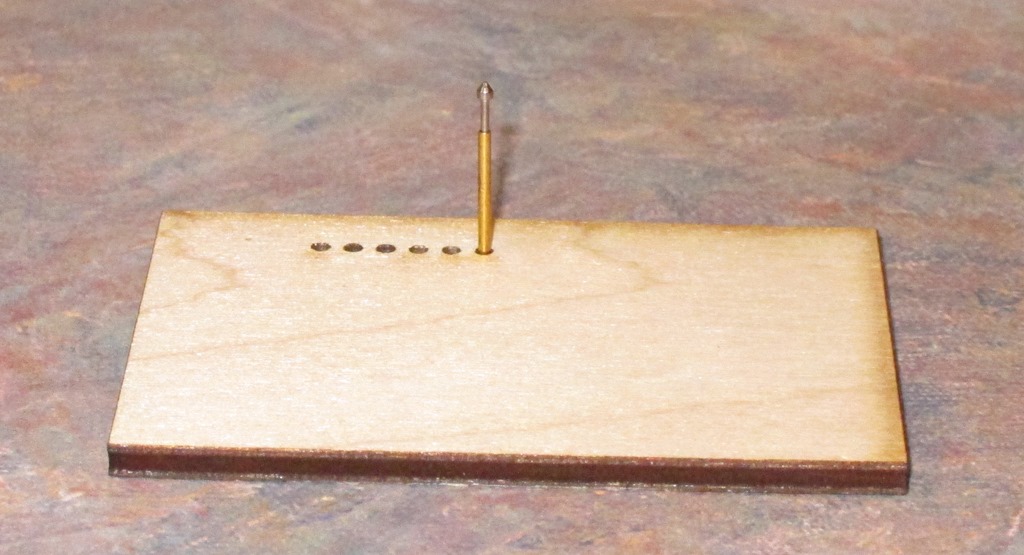
IMG_9553

The test fixture cut out of 0.1” (2.6mm) maple plywood.

The 0.875mm hole is the only one that is close; it’s a tiny bit snug in the middle (the laser beam is shaped like a very tall “X”, so the hole is thinnest at the focus point in the middle and a little bigger at the top and bottom).

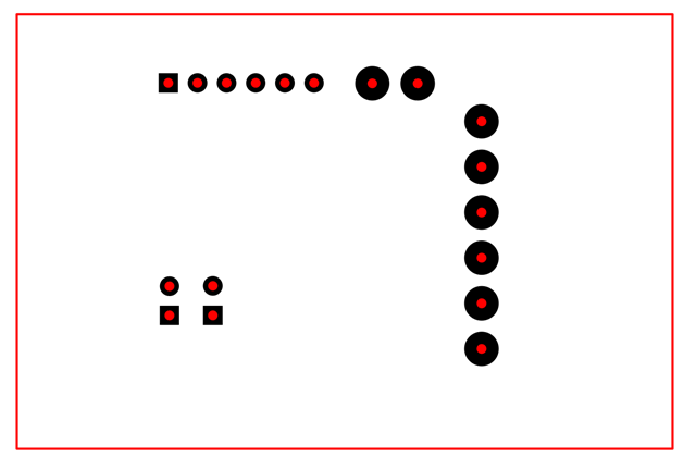
Based on the step in sizing between holes, I’m going to size them all to 0.85 mm.

image

That’s the completed design. In my laser cutter (a GlowForge), it groups the elements by color, so it’s easy for me to tell it to cut the red circles and not the black pads. If you want to simplify the cutting part, you might want to delete the pads.

Back to the cutter.

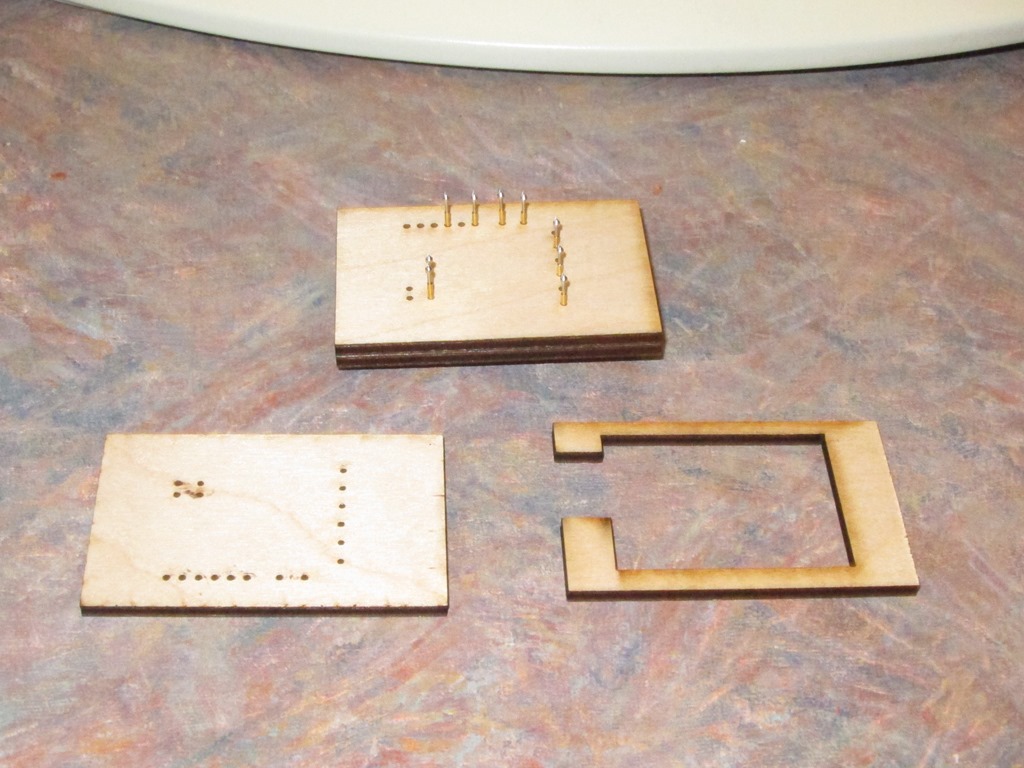
IMG_9554

I cut 3 identical plates plus a spacer. The stack will have two plates with holes, then the spacer level where the wires will be soldered to the pins and finally a plate at back. The wires will all come out through the spacer holes on the left. It’s hard to tell from the picture, but the pins are inserted so that they stick out the back enough for the bottom of the pin to be flush when the spacer and bottom plate are added.

Oh, and that lower-left piece is upside down…

Next is hooking up the test wires. There are 22 pin holes, but two of them need only to be bridged and seven connected with wires for testing.

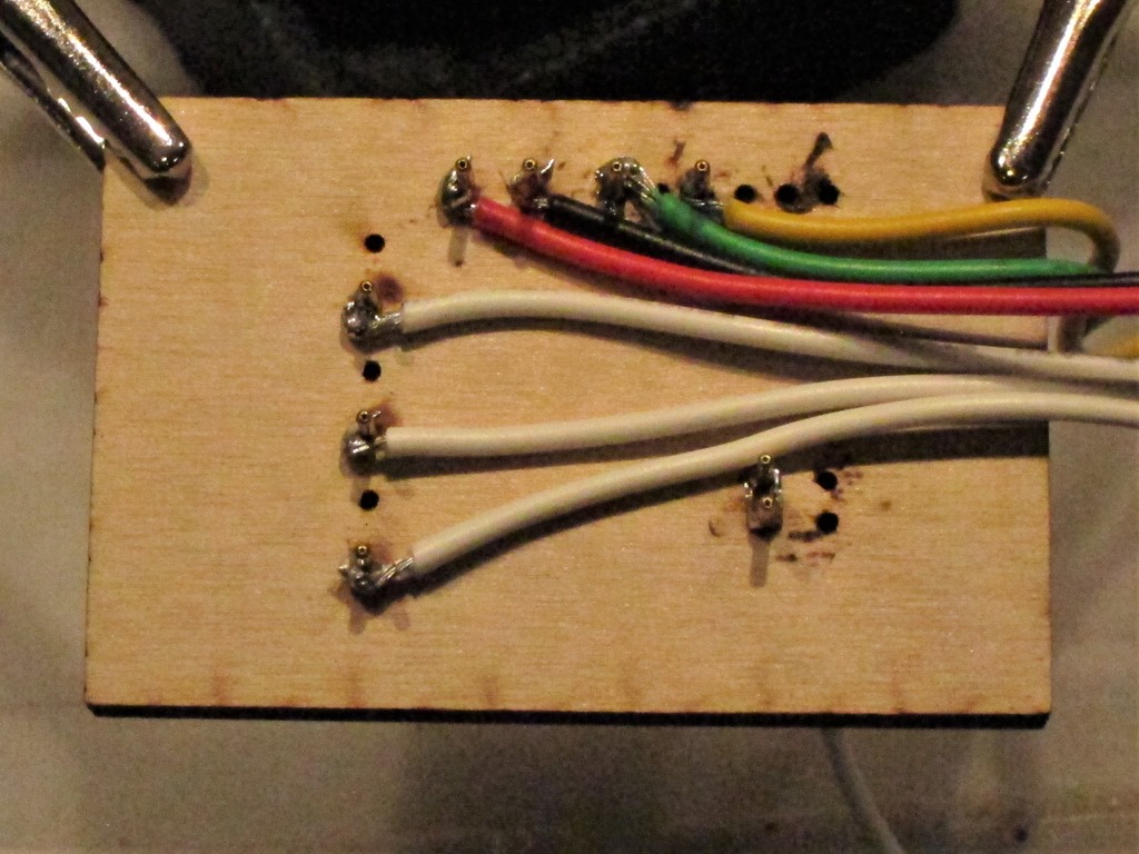
IMG_9560

That’s a rather poor picture of the wires attached to the pogo pins. After they are all soldered on, the back piece goes on and then I taped it together with blue tape so the pieces are apart.

That would normally be the last step, but the high-current pins on this board are set up using 3.96mm headers instead of the 2.54mm that my pogo pins are designed for, so those pins just go right through the bulbs. With a little bit of play using a soldering iron, you can get a blob of solder on each of those pins and then it will work fine.

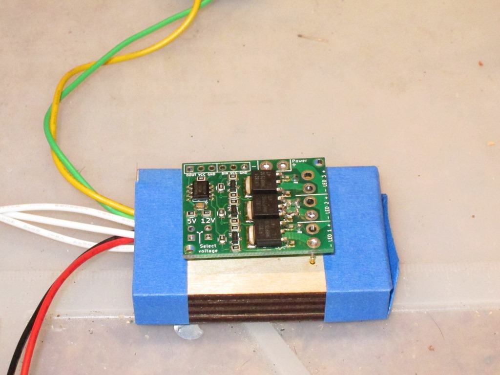
Here’s the completed tester with a board just sitting on it.

IMG_9562

The yellow and green wires come from an ESP8266 that I use to drive it, the red and black are 12V power from a repurposed XBox 360 power supply, and then the white wires are the grounds for the loads (the board provides both positive and ground for each LED, but I only need the grounds to do the testing).

I made a quick video showing the tester in action.


MVI_0093 from Eric Gunnerson on Vimeo.


EagleDecorations Ornament Creation Instructions

Thank you for buying one of our ornament kits. These are the generic instructions that apply to all of our ornaments; please look at specific instructions for your kits for more details.

Tools & Supplies

You will need the following supplies:

  • A small soldering iron
  • Solder
  • Needle nose pliers
  • Diagonal cutters or other tool to trim leads and wire
  • A power supply for the kit your ordered – either a 5V USB charger or a 12V power supply.

LEDs and Resistors

To keep LEDs from burning up, we will be including resistors that will limit the flow of current through the LEDs and equalize the brightness between different ornaments.

Depending on the color of the LED that we are using the the voltage we are using for the ornament – either 5 volts or 12 volts – we will be connecting chains of 1, 2, or 4 LEDs to a single resistor. The instructions for your kit will tell you how many LEDs to put in the chain for each resistor. If there are multiple colors in your ornament, each color may use a different number of LEDs in the chain.

Creating chains

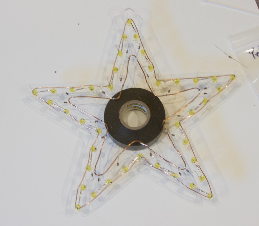
Here is an example of creating chains of 2 or 4 LEDs, taken from the yellow star ornament:

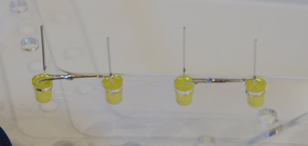
IMG_7062

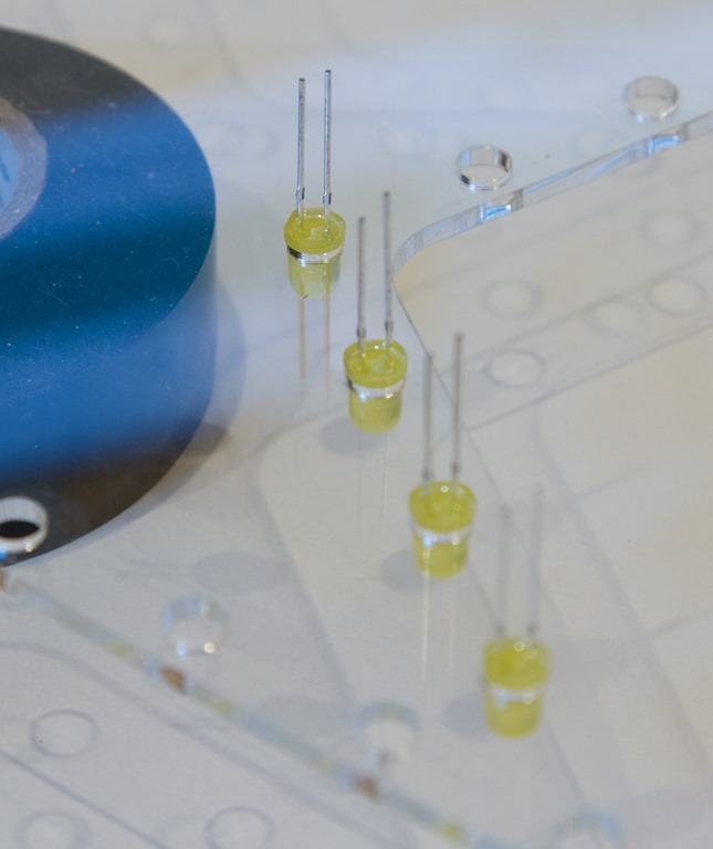
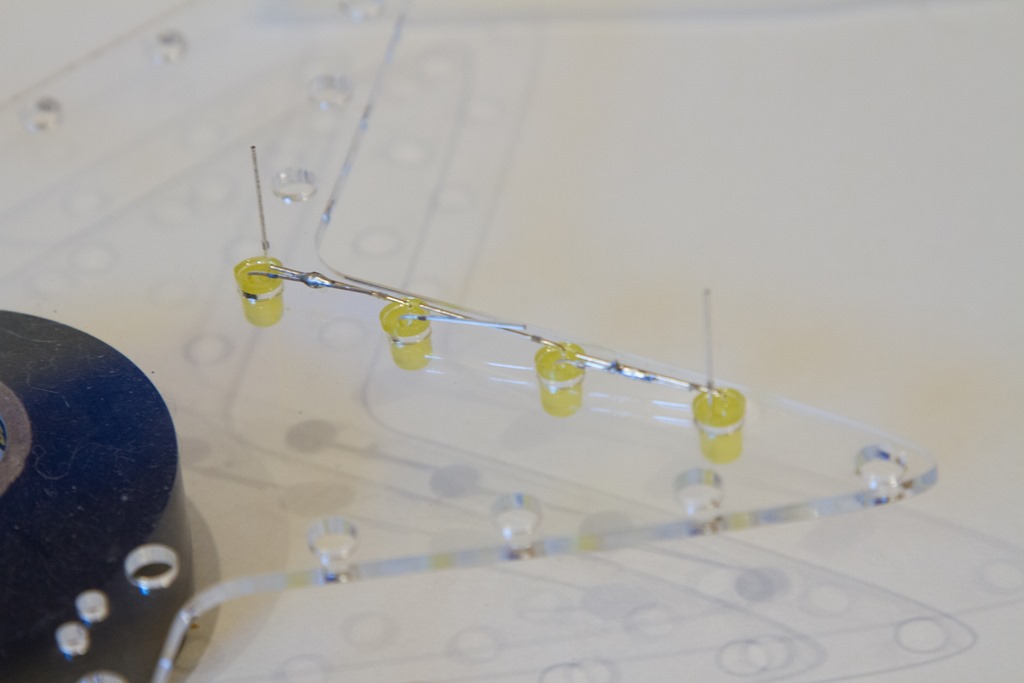
Note that the LEDs are placed with the longer lead towards the outside of the ornament. That is the basic pattern we use for all of the ornaments.

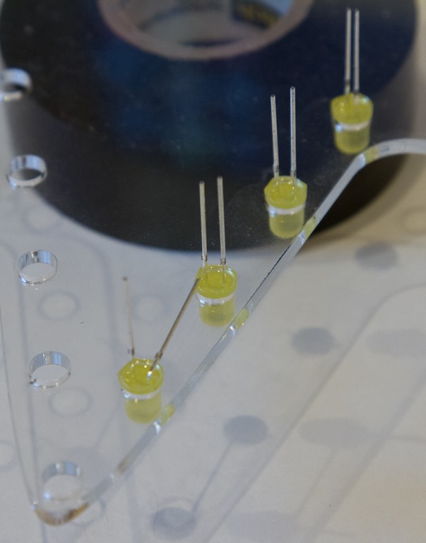
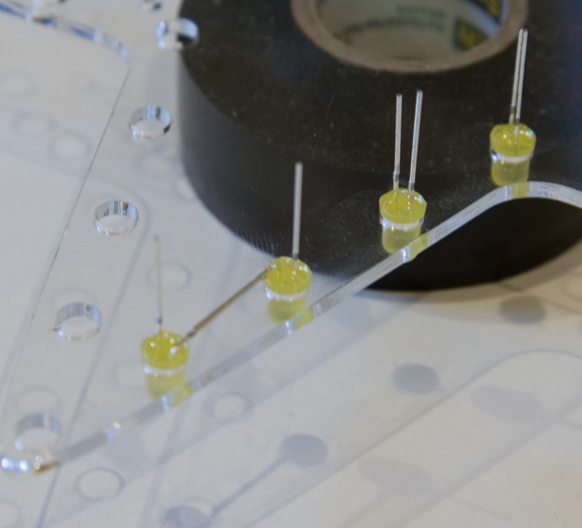
IMG_7063IMG_7064

In these pictures, we are making chains of 2 LEDs. In the left picture, the longer lead on the closest LED is bent towards the shorter LED of the next LED. In the second picture, the short LED on the second LED is bent back towards the long lead from the first LED. Connections between LEDs should always be done in this manner.

Here is what it looks like after creating two chains of 2 LEDs:

IMG_7065

A 4 LED chain looks like this, with 4 LEDs connected in a chain.

IMG_7066

A full set of chains

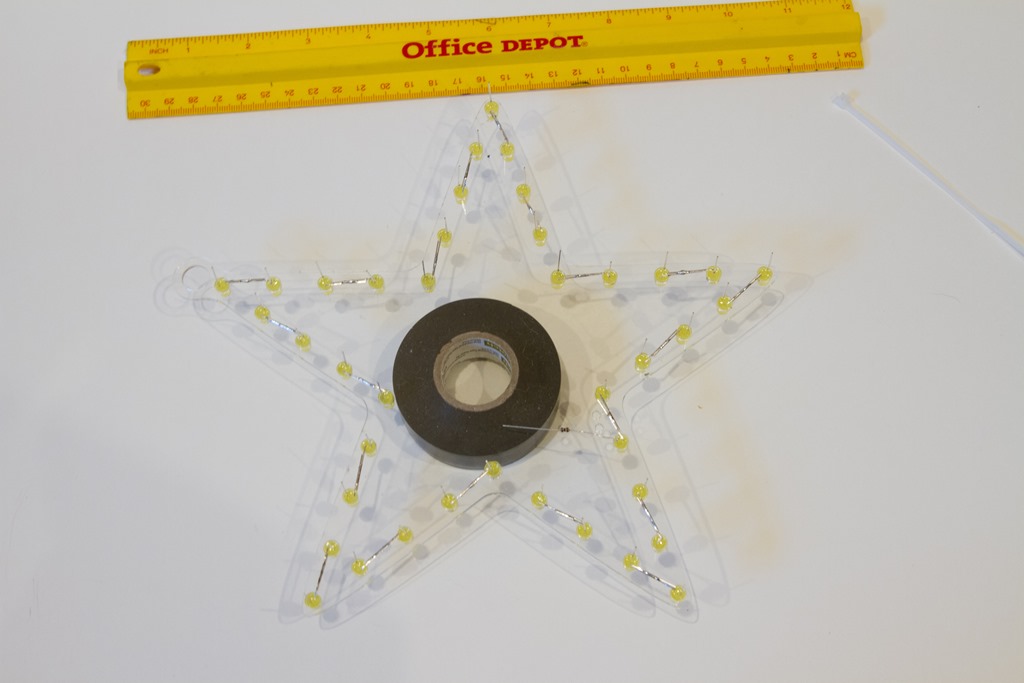
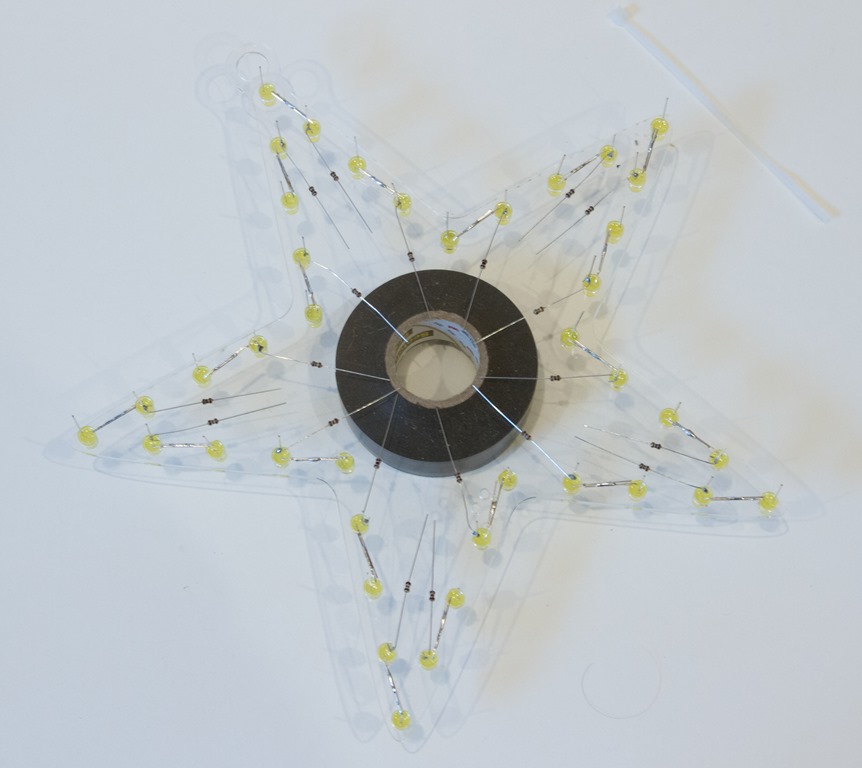
The outline of an ornament will be a series of chains; it will look like this:

IMG_7068

Adding resistors

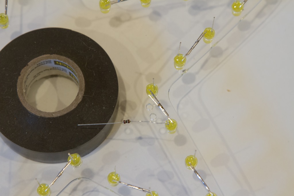
After the chains are created, we will need to add a resistor for each chain. The resistors are always connected to the inside (shorter) lead at one end of the LED chain:

IMG_7069

When all the resistors are connected, it will look like this:

IMG_7070

Hooking the chains together

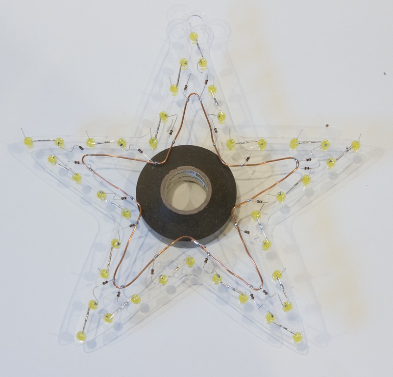
The next step is to hook all of the chains together. We will do the insides first. This is done with some of the bare copper wire included in the kit. Start by taking the wire and bending it into a rough approximation of the template, and then put that inside the wire.

We will be connected the currently unconnected end of each resistor to the bare wire.

IMG_7071

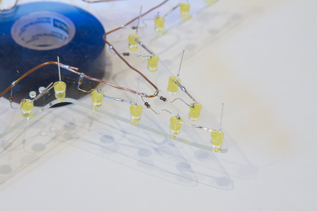
As shown in this picture, you may need to reroute the resistor wire a bit to make it easier to connect to the bare wire. Here’s a close up of that:

IMG_7072

Once all the resistor wires are soldered on, trim the resistor wires. Next up are the outer wires. The outer wires run around the perimeter of the LEDs and are soldered to the remaining unconnected LED lead. Make sure the outer wire does not touch any other wires.

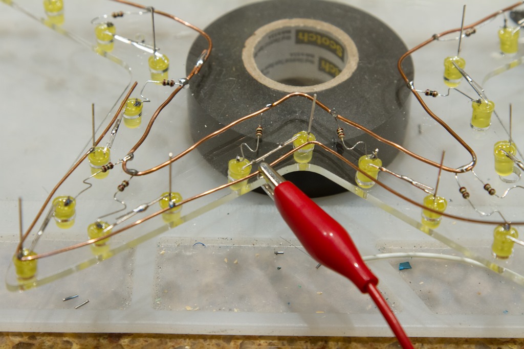
It is very useful to clamp the outer wire down as you are routing it around. I use a little alligator clip:

IMG_7074

Here’s what it looks like when finished:

IMG_7076

At this point we would test by applying the appropriate voltage to the inner and outer bare wires.

Adding the power cord

Locate the power cord – either the USB one with the 5V kit or another one if you are building the 12 volt version.

At the bottom of the ornament, you will find two tiny laser-cut holes. The are for the zip-tie that will hold the power cable in place. Pass the zip-tie from back to front and then to the back again, place the power cable in approximately the location you want and lightly secure it with the zip tie. Solder the power cord wires to the two bare wires, verify that it works, and then tighten the zip tie. Cut off the extra.

Success! You have completed the ornament:

IMG_7080

Protecting the wires

The wires only carry low voltage, so there is little shock hazard.

If you want to waterproof the ornament, I have had good luck with 100% clear silicone sealant. Make sure to cover the base all the LEDs and over and under the resistors and all wires. This approach has survived multiple holiday seasons outside in wet and cold weather, but there is no warranty for outside use.


WS2811 Expander Part 6: of MOSFETS and voltage drops…

After I wrote the stress test article, I decided to put a voltmeter across the drain and source of the MOSFET and figure out what the voltage drop was. I hooked up the output to an LED ornament, watched the brightness cycle up and down, and put my probes on the MOSFET.

What I expected was pretty simple. In the sweet spot of the MOSFET I’m using, it claims a Rds – resistance between drain and source – of 10 milliohms. That means I should expect a voltage drop at 5 amperes of:

V = 0.01 * 5 = 0.05 volts

That low voltage drop is one of the reasons to use a power MOSFET; a bipolar transistor would have a voltage drop of about 0.6 volts, and therefore waste more power and get hotter.

The voltage jumped around a little, and settled down at full brightness:

0.8 volts

Okay, that is really unexpected; I played around with different voltages, and I still got 0.8 or 0.9 volts.

My first thought was that the MOSFETs that I got from Ebay might be counterfeit, so I waited for my order of real parts to show up from Arrow, built a new board, and it read:

0.85 volts

This is really confusing, so I asked a question on Reddit’s /r/AskElectronics subreddit.

The first answer I got was that it might be the base diode because I had the MOSFET backwards.

So, I pulled out the datasheet for the MOSFETS and looked at my schematic and board in Kicad. As far as I can tell, everything is wired correctly.

A deeper answer suggested that if I was doing PWM (I had been testing at brightness = 250 because I knew that would be more stressful for the MOSFET than always on), I should test with always on. It also talked about gate capacitance.

<digression>

This is one of those cases where real devices diverge from ideal devices. FET stands for “Field Effect Transistor” – current through the source and drain is controlled by the field on the gate. You establish a field by the flow of current to charge it up to an appropriate voltage.  The amount of current it takes depends on the gate capacitance (described as “Input Capacitance” on the datasheet). For the MOSFET to turn on, you need to flow enough current to establish whatever voltage you want on the gate.

Or, if you think of the gate as a capacitor, it takes a bit of time for it to charge. In my case, the time it takes to charge will be controlled by the pull-up resistance and the capacitance.

Let’s say we are running at 5V, and our MOSFET has 1nF input capacitance (pretty close), and we are charging through a 10K capacitor.

This calculator says that the time constant is 0.00001 seconds, or 10 microseconds.

</digression>

So, I went and changed the animation code to run all the way to full on – luckily my code is running on an ESP8266 and animations can be changed over WiFi – and rechecked the voltage drop.

Would it surprise you if I told you it was 0.8 volts? Probably not at this point…

Perhaps it’s my voltmeter; I have a nice Fluke but how about if I try using my oscilloscope (a Rigol DS1102D I picked up a while back)?

So, I powered it up, hooked it up, and looked at the waveform across the load. I showed the a nice PWM waveform…

But wait a second… I had updated the animation.

My debugging rule is that when things seem unexpected, back out a level and retest the assumptions. Usually one of those is wrong.

I started with my controller code. I suspected the gamma mapping code, so I added some Serial.println() statements and verified that, yes indeed, the colors were getting set to 255. So, that part was fine.

I next suspected the support library I use (the rather excellent NeoPixelBus). I read through a bunch of source but didn’t seem to be any issues. The code all looks fine…

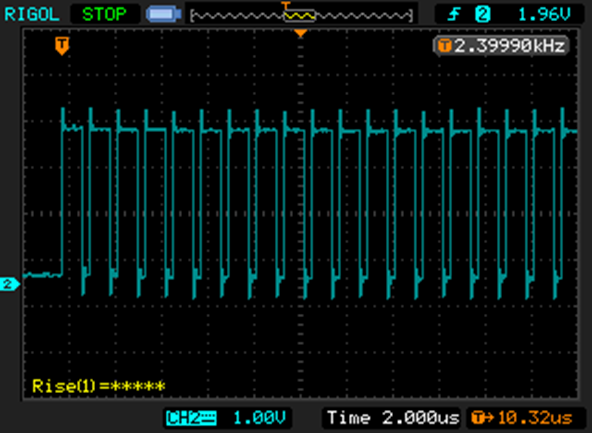
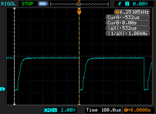
Was the data getting to the WS2811 correctly? So, I fired up the scope again and hooked it to the data line. On full on, the data looks like this:

NewFile0

The WS2811 uses an encoding scheme where a short positive pulse means “0” and a long positive pulse means “1”.

That is a full string of ones; you can’t see all 24 of them, but trust me when I say they are there. You can see this switch back all the way to all zeros as the animation progresses.

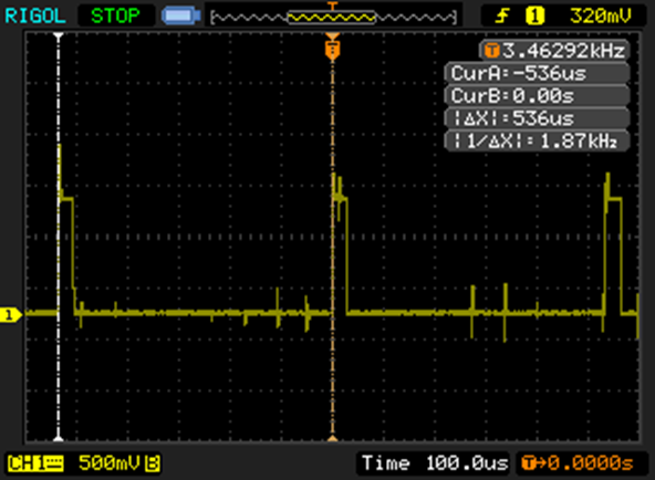
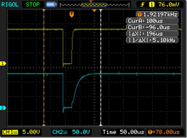
So, the software is telling the WS2811 to go to full bright, but it is still turning off for part of the cycle. Here’s the output straight from the WS2811:

NewFile4

That little positive spike is 29.4 microseconds, which is about 5% of the 536 microsecond cycle time, so full bright is only 95% bright.

The cursors on the capture show the start of two sequential PWM cycles, and the scope nicely tells me that it’s updating at 1.87 KHz. Which is another weirdity, since every source I’ve seen suggests that WS2811s update at 400Hz.

At this point I’m beginning to wonder if I have a WS2811 clone. I thought it might be the same IC used in the SK6812 ICs, but the claim is that they have a PWM frequency of 1.1KHz which is less than I am seeing.

So, it’s off in search of some real WS2811s. It is really easy to buy cheap ICs made in China but is surprisingly hard to find an authorized source. There are lots of sources on aliexpress, some looking pretty shady. Octopart found me a 10-pack from Adafruit for $4.95. I finally found lcsc.com, which specializes in this sort of thing, and ordered some. They look to be WS2811S chips, but I can’t find any information on what the “S” means. More on that when they show up.

Back to voltage drop…

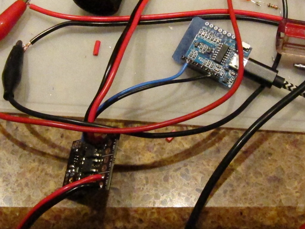
Since the WS2811 wouldn’t go into “full on” mode, I needed a test setup to do my testing. Here’s what I came up with:

image

In the right middle is the MOSFET, with clips connected to the lead and the body. In the picture, it is running only the LED Star, which pulls 145mA of current.

One of the fun things about MOSFETS is the gate holds onto the charge, so if you just touch the gate to 12v, it turns on and stays on. Touch it to ground, and it turns off, and stays off. I measured the voltage drop across the MOSFET.

I next decided to hook up my test load. I started with a single 50 watt bulb, a 4 amp load. I carefully hooked it up in parallel with the led star, and…

There was a loud “crack” and the led star went out. No magic smoke, but the MOSFET was toast. The gate was floating, and there wasn’t enough charge there to put it firmly into full conduction, so it was in the linear zone and quickly overheated, melting the plastic on one of my clamps. So… replace the MOSFET, make sure the gate is attached to positive, and try again. That worked, and the MOSFET was only mildly warm. Let’s try two bulbs for an 8 amp load. That worked, *but* there is no heatsink and it got hot pretty fast, so I unplugged it before it got too hot.

I collected some data and figured out that the Rds was about 90 milliohms, which is a lot higher than the 10 milliohms I expected. That was a mystery for about 8 hours, until I was writing this up and realized that I was measuring the voltage drop at the ends of the leads connected to the MOSFET. The thin leads.

So, I went back and measured right at the MOSFET, and got a Rds of 7 milliohms, a bit better than the 10 milliohms that was spec’d. So, yay!

Faster switching

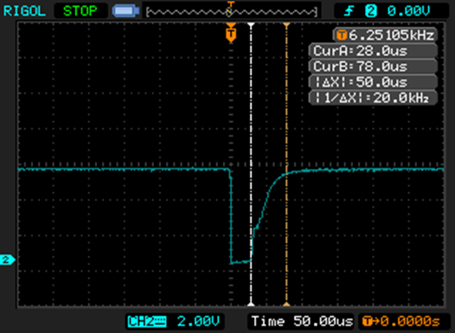
Returning to our somewhat slow switching, here is what I saw:

NewFile2NewFile3

The negative transition is when the transistor turns on; notice how effortlessly and quickly it pulls the gate voltage down. And when the transistor turns off, note how long it takes it for the gate voltage to charge back up. It’s roughly 10% of the overall cycle time.

Which is a bit embarrassing; I chose the 10K value as a typical pullup value, not thinking about the fact that this was happening on every PWM cycle. It can only supply about 1 mA of current.

The most obvious thing to try is to replacing it with a 1K resistor. That will result in 10mA of current and should switch roughly 10 times faster. Can the transistor handle it? The datasheet says that the 2N3904 can handle up to 200 mA continuous, so that will be fine. Is the base resistor okay? Well, transistor has a DC current gain of at least 50, so that means we need a base current of 10mA / 50, or 0.2mA. The 5V from the WS2811 will push about 4 MA through the 1K base resistor, so that’s way more than enough. It would probably be fine with a 10K base resistor, actually.

I took one of the boards and replaced one of the 10K resistors with a 1K resistor and then looked at the gate drive:

NewFile5

In case it’s not obvious, the top version is with the 1K resistor and the bottom one is with the 10K resistor. More than good enough for my application.


WS2811 expander part 5: 12V stress test…

One of the points of the expander is to be able to drive bigger loads than the 18mA that the WS2811 gives you directly. Much bigger loads.

To do that, I needed something that would stress the system, and I needed to verify that the design worked with 12V.

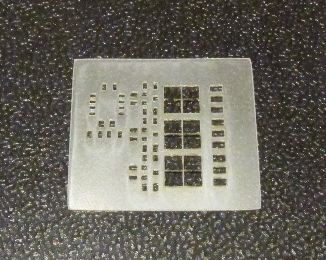
First off, I needed to cut a new stencil uses the paste layer:

IMG_9501

That’s a bit nicer than the first one; there is adequate spacing between the pads this time.

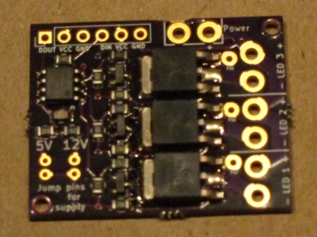
Aligned it on the board, applied paste & components, and reflowed it. Here’s the result, still warm from the oven:

IMG_9502

All the components self-aligned nicely, no bridges, no missing wires. Perfect.

The only thing I need to do is get rid of the center pad for the MOSFETs, since they don’t actually have a center pin.

How to test it?

Well, I dug through my boxes and found a 5 meter length of 12V LED strip. It says that will be 25 watts. I hooked it up and verified that all 3 output channels are working. It’s running an animation that ramps from 0 to 255 over 2 seconds, holds for 2 seconds, and ramps down for 2 seconds. I chose that because the quick switching is the hardest for the MOSFET to deal with from a heat perspective.

But 2 amps isn’t quite enough. I dug out a 12V power supply that claims it can do 6 amps and hooked it up to one output channel:

IMG_9504

That’s the NodeMCU board in the upper right, powered by LED, the data and ground running to the board, and then some decently-hefty wires running to the board.

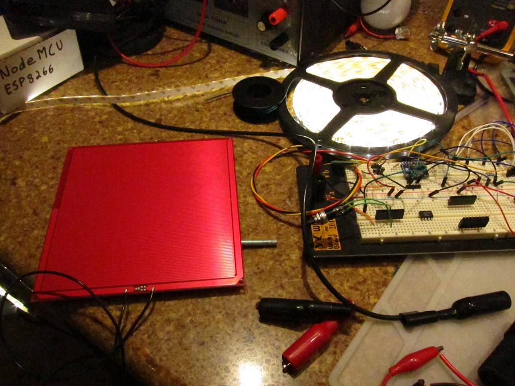
More load, more load, more load. I want something that soaks up the 12V. Incandescent car bulbs are nice but I don’t have any handy. But I do have an extra heated bed for my 3d printer; it’s a nice 6” x 6” pc board. Hooked that up in parallel with the lights:

IMG_9505

Ignore the breadboard…

This worked just fine. The board heated up to about 170 degrees, the lights worked fine, and the MOSFET on the driving board just *barely* heats up. My measurements show that it’s switching about 5 amps of current.

The only one that’s not happy is my cheap power supply, which is putting out a nice 10Khz (ish) whine when under load.

I switched over to run it on all the time to see how that affected things. After 10 minutes, the board is up to about 110 degrees, the printer bed is up to 240 degrees, and the 12V power supply is 125 degrees.

I think I’m going to rate it at 6 amps total; that gives a lot of margin, and frankly 70 watts is quite a lot of power for this application.


WS2811 expander part 4: Boards and Parts!

After a bit of waiting, the boards showed up from OSHPark. they looked fine as far as I could tell.

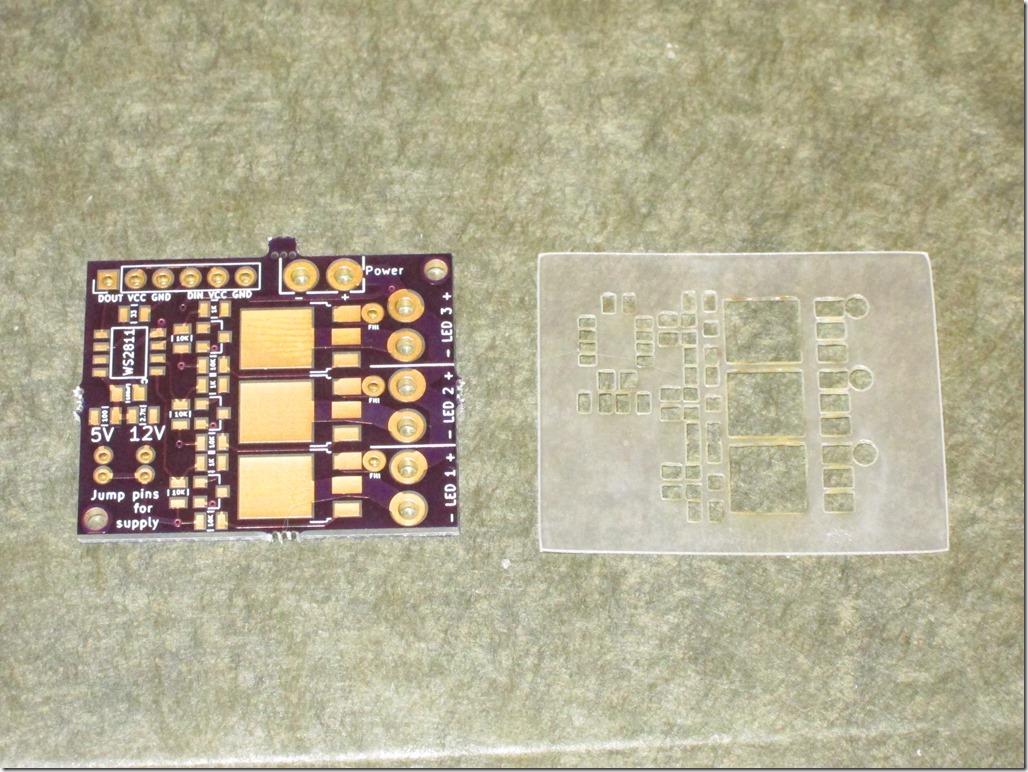
I had all the other parts to do a board, but I needed a paste stencil. I went into pcbnew, chose File->Export, and then chose to export the F.Mask (ie solder mask) layer to a SVG. I cleaned it up a bit to remove non-pad elements, went out to the laser cutter and cut a stencil out of 4 mil mylar:

IMG_9495

Everything looked pretty good; there was good alignment between the board and the stencil. The spacing between the pads looked a little tight, but it’s a fairly fine pitched board, so it was mostly what I expected.

I carefully aligned the stencil and taped it on, got the solder paste out of the fridge, and applied it. Pulled up the stencil and it looked crappy, scraped it off, did it again, and got something that looked serviceable though there was more paste than I expected. Hmm.

Got out the components:

  • 1 WS2811
  • 1 33 ohm resistor
  • 1 2.7k ohm resistor
  • 6 10k ohm resistors
  • 3 1k ohm resistors
  • 3 NPN transistors
  • 3 MOSFETS
  • 1 100nF capacitor

and it took about 5 minutes to do the placement. Here’s the result:

IMG_9496

I didn’t look at the picture at the time, but that’s a *lot* of solder paste.

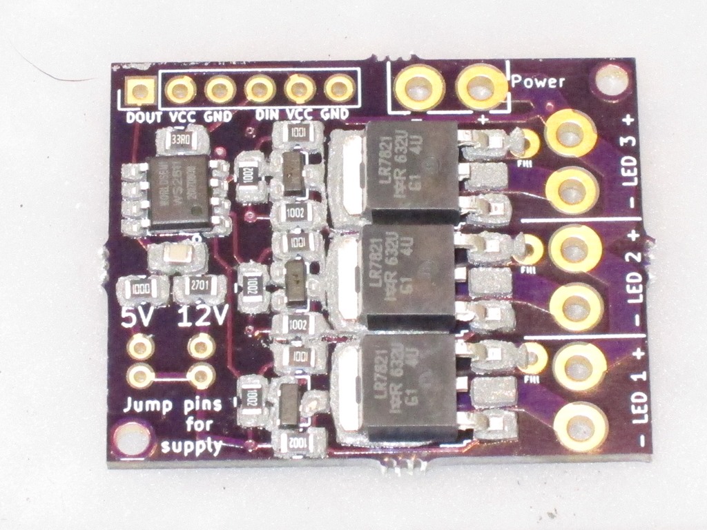
Into my reflow oven (Controleo 3 driving a B&D toaster oven), let it cycle, seemed fine, here’s the board:

IMG_9499

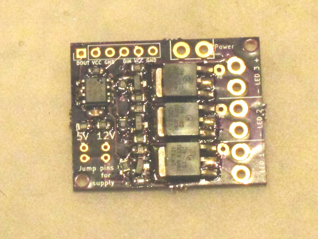
Not my best work. Frankly, it’s a mess; there are obvious places where there is no solder, and obvious pins that are bridged together. I spent about 15 minutes with my VOM testing for continuity and there were 3 solder bridges and 7 unconnected section.

Something clearly went wrong. And I went back to PCBNew and it was *really* obvious.

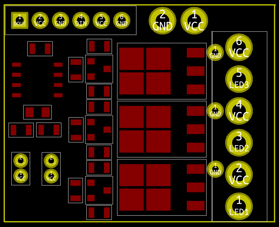
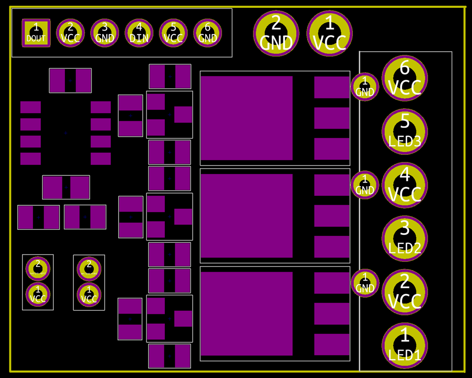
The layer you should choose for your stencil is F.Paste, not F.Mask. Here are the two next to each other (Mask left, Paste right):

imageimage

The Mask layer sizes are positively giant compared to the paste ones. So, what happens if you use the Mask layer is that you have:

  • A *lot* more paste on the board, especially the small pads which must have double the amount
  • Solder paste with much reduced clearances.

What that means in reality is that when you put the components on, it squishes the solder paste together and connects pads that shouldn’t be connect. And then when you head it up, you either get bridges or one of the pads wins and sucks all the paste away from the other pad (how it wins isn’t clear, but it is clear that the huge MOSFET pads pulled all of the paste from the transistors next door).

This makes me feel stupid, but it is actually quite good news; it means that the design is fine and I just need to remake a stencil with the correct layer.

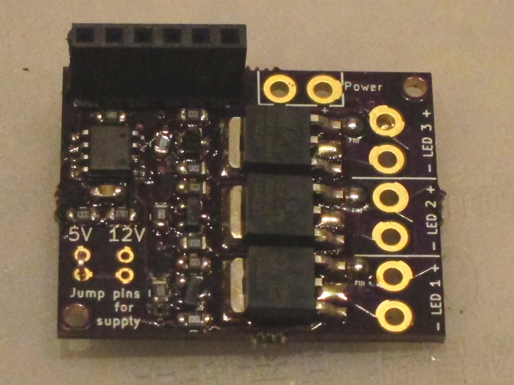
Anyway, after a lot more rework than I had expected, I ended up with this:

IMG_9500

It’s still an ugly board, but does it work?

Well, I hooked up 5V, GND, and data in to one of my test rigs and a LED to the LED outputs.

And it works; the LED is on when I expect it to be on and off when I expect it to be off. All three outputs are fine.

The next test will be some testing to see how it fares with switching high current. And I’ll probably want to make another one using the correct stencil and hook it up for 12V operation to verify that.