Browsing posts in: Electronics

Snowflake update…

Have made decent progress on the snowflake. I have two PCBs assembled and populated. The right way to do it would be to use a reflow oven, but I’ve settled on using my new hot air rework station and solder paste to do the data lines – since the pads that I need to connect are tiny – and hand soldering everything else, including the LEDs. I did reflow on a test LED and it worked, but I had to get things hotter than I would like.

I finished the outline design and cut the snowflake fronts from white acrylic. This was a bit frustrating; the Glowforge is advertised as being able to cut about 11.5″ in the forward/back direction, but they haven’t been able to achieve that, so I had to cut slightly smaller than I wanted.

I used one sheet each of #7328 and #2447 acrylic so I could see which one I liked better:

IMG_8876

After playing around a bunch (something like 15 variants) with both plastics and with keeping them different distances from the LEDs, we settled on 2447 spaced about 10mm away.

Then it was off to Tinkercad to design a clip that would hold the front to the pc boards, which finally led to this. You can see the clips (printed in clear PLA) holding the snowflake at the right distance.

MVI_8888 from Eric Gunnerson on Vimeo.

After a false start or two, I think I have a handle on how I want to structure the animation code; it’s nice and mathy…

Now I just need to order some more Huzzahs to drive the other snowflakes, figure out how I’m going to handle the cabling, and buy some waterproof 12V –> 5V buck converters (I’m tired of worrying about voltage drop).

The video is powering the LEDs from a USB port using tiny wires, and the 5V supply is sagging down to around 4 volts because of the load. So, it will be brighter than this.


Snowflake #2–PCB design

I thought that I was done with the PCB design, but it turns out that I wasn’t close.

Basically, I ran into two big issues.

The first was the wierd angles that I had in my design; they didn’t pack together very well. What I really needed was a way to rotate the two short arms so they were at 90 degree angles.

I couldn’t find anything, so I went and wrote a utility to do it. On the way, I learned a lot about the KiCAD file format. It was a nice little exercise; I’ll note that it’s in pretty rough shape and you would need to recompile it to get the rotation you wanted (and to work on the file you wanted); maybe I will clean it up at some point. It’s C# code because that’s what I speak best.

I guess I should also note that I built a little .pcbnew parser to do it; it parses the file into a bunch of nodes, you change the ones you want to change, and then it writes the file back out the way it was before except for the changes. So, it will likely be useful for other stuff as well.

So, anyway, that gave me everything at increments of 90 degrees, which was good. Then I went off and started trying to understand if PC fab houses could build what I wanted. The answer seemed to be “yes” (though not in the current form), but they would likely charge extra and there was a decent chance they would make a mistake. The problem is that I have 4 different irregularly-shaped boards. You can’t use v-groove panelization because that only works with (mostly) rectangular boards. I was hoping to use the GerberPanelizer, but I couldn’t get any of my boards to show up in it; I suspect it’s because of their shape.

So, I went off and taught myself the requirements and spent a bunch of time coming up with this:

image

This is a hand-panelization of my boards. The idea is to come up with a design that can be fabricated as a single piece by the fab (and assembled/soldered/etc., if you are planning on having somebody do that) but can still be easily separated.

You do this by putting little breakaway tabs with small holes (I used large vias because KiCAD only supports holes in footprints). The idea is that after you get the pcb, you can carefully break off the parts with the weak tabs to separate the boards. The tabs are also called “mousebites”.

To make them breakable, you need to design things so that you have multiple tabs that are in a line and could easily bend. That isn’t even close to possible with this design, so what I’m going to do is cut the boards apart with my Dremel rotary tool or oscillating multitool. The rough edges will not matter for this application. If the design is correct, all the yellow edges will be cut with a router after the PCB is etched.

Oh, and the small boards on the right are little WS2812 breakout boards; I had a bunch of extra space in the square, so I added them in.

My first check is to upload to OSHPark and see what it thinks; I’m not going to order there but it does full visualization of the boards. Here’s what I got for the board and the board outlines:

Yeah, that’s not very good. The design looks fine. However, when I was switching between layers, I accidently chose the “Eco2.user” layer instead of the “Edge.Cuts” layer. They are rendered in the same color. All I needed to do was to turn off that layer, and then I could flip those lines over to the edge cuts layer, and that fixed the issue.

OSHPark still has trouble with the design, but I’ve exported Gerber files (one file per layer in the design tool) and looked at them in other viewers and they are fine. I think the OSHPark viewer is having trouble with the internal cutouts.

Because of the complexity of the design, I’m not sure how to spec it on the online ordering tools, so it is currently out to order.


Snowflake

For the last 5 years or so, I have led a “Holiday Lights Bike Ride” in early December. It’s fun to tour around and look at lights on a bike, and the view you get on a bike is very different than in a car.

One of the houses has a large snowflake with white and blue lights. Very nice and pretty.

After four years of service, I retired the LED strips I had along my gutters. The “waterproof” strips had started shorting out and it was a pain to replace sections. I personally liked the “line of light” look, but the vast majority of people didn’t even notice that they changed color.

My first thought was to replace them with WS2812 strips, so that I could address all of them. I played around with a few designs, but didn’t solve the design problems to my satisfaction; coming up with a way to keep the strips actually waterproof while still supplying them with power (which you need every 2.5 meters) was a hard problem. So, I put that project on the back burner.

A while back, my Glowforge showed up, and that triggered a new thought about the snowflakes. Instead of doing addressable LEDs on the gutter, could I do snowflakes that hung at gutter level? And then do the gutters with some nice traditional C9 LEDs.

Here are the basic parameters that I came up with.

  • Addressable LEDs (probably WS2812s)

  • Snowflake outline in acrylic (because I can cut it on my glowforge), white so that the color spreads out, and something like 12″ across (a little small, but it’s an easy size to deal with, and larger sizes make it harder to deal with the wind storms we always get).

  • Around 50 LEDs per snowflake

  • With local 5V power supply. I’m tired of running 10 gauge cable and worrying about voltage drop, so I want something regulated and local. It will probably be a local 12v to 5v converter, though I might end up with local AC instead.
  • Microcontroller controlled. That was obvious with the ws2812 choice.

  • *Maybe* WIFI controlled. I’m thinking maybe 8 of the snowflakes, and I can do an ESP8266 across that many relatively cheaply. That would let me drive them in sync from the comfort of my office machine.

The snowflake design was pretty simple; it had to be so that I could easily light it with LEDs.

One of the truisms in these projects is that it’s always the wiring that is the most painful part. That almost killed me on the Snowman project; lots of individual wires, and each has to be cut, stripped, and soldered. Not fun.

I’m thinking about doing 8 of these, so that would be 8 * 50 (leds) * 4 (connections), or something like 800 wires and 1600 solder joints. And to compound that, you need decent sized conductors so that you don’t lose too much voltage along the way.

The way to get rid of all the point-to-point soldering is to use a PC board. Since boards are priced based on their area, I explored using APA102 LEDs which are available in a 2020 package.

That’s 2mm x 2mm, or just a little bit more than 1/16” square. I’m planning on soldering with a heat gun (or maybe I’ll pick up a cheap hot air rework station), but the 2020s will be blown right off the board.

So, it was back to the 5050 (5mm x 5mm) package, and at that point the WS2812B won out on cheapness. The APA102s are nicer but much pricier. Oh, and they have separate clock and data, which is one more wire to try to route correctly.

And there I ran into a problem. A run of eight 12″ x 12″ boards would be right around $200, which is a bit pricier than I had hoped, and it’s not clear to me that I could find a fab that would be able to cut such a fragile arrangement of boards; in fact, I was pretty sure I couldn’t find one.

After some thought, I realized that I could do the snowflake as a series of boards; a central board, 6 straight boards that attach to the central board, and 12 arm boards that radiate from the straight boards.

After a bunch of iterations, it ended up looking like this:

image

And yes, I did notice the resemblance:

Image result for klingon warbird drawing top view

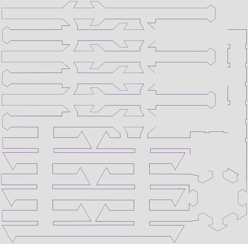
I took that design, pulled it apart, duplicated parts, and came up with this layout:

image

The PC board will be a little bigger because I’ll need tabs between each part, but it will be close. That is about 5” x 5.3” and has all the parts for a 12” snowflake.

But would it work? Well, a trip to the glowforge with a piece of cheap plexiglass and two minutes of time yielded enough pieces to test it out (the rest didn’t cut cleanly because cheap plexiglass):

image

The laser loses a bit of material in the kerf, so they are a bit loose, but that will be better with the real design, and it isn’t structural; all of this is supported by the acrylic snowflake, which is thicker and beefier.

It was time to do some board designing. Unfortunately, I don’t have a full license to Eagle, and the free version won’t let me design boards that big (actually looking at the new Autodesk free license, I probably would have been fine), so that meant I had to teach myself KiCAD. Like Eagle, it has a bunch of weird eccentricities which are of course different than the ones Eagle has, and I’ve spent a lot of time researching how to do things that are very simple.

The circuit is really very simple; just power, ground, and a daisy-chained data line. The only big constraints are:

  • I want big traces to limit the voltage drop
  • I need to be able to connect from one board to another

My usual approach for PC board design is to draw the schematic, and then just start playing around with layout. The layout of LEDs is pre-determined, so it’s really just about routing all the conductors.

Here’s a very ugly schematic:

image

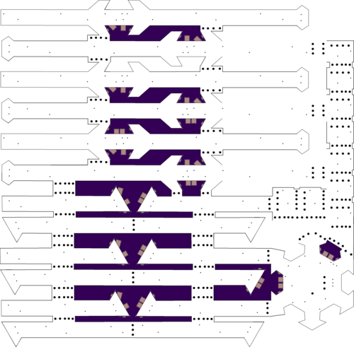
I luckily forgot to save my early versions because they were pretty bad, but with a lot of refinement and rework, here’s version 0.9.

image

The fat green VCC and GND traces are on the underside of the board, and then the thin red traces (or yellow if there are green lines behind) are the data lines. Wherever there are breaks between the boards, the are solder pads that span across the boards; the idea is that those will be soldered to hold the boards together.

The hub on the right was an interesting challenge; I need to design the pads and place the pads for the other 5 arms so that they will correctly align with the one arm that I did design.

Here’s a close-up of the hub:

image

The yellow line is the board edge, so what what I have is pads that hang halfway over the board edge and out into space. You will see some small little blue dashes; those are used to align the pads properly on the cutout.

If you look at the little red data line pads, you’ll see that they aren’t so well aligned. I think I’m going to need to redesign those pads with the same alignment marks so they can be better aligned. Then I’ll have to tear out most of the data lines and the old pads, rotate each new pad to the proper angle (each one is different because of the shape of the recess), and then redo all the tracks that run to them.

Such is the nature of PC board design; you think you are done, and then you need to do a bunch of re-routing.

Luckily, the tool helps out a lot; the system knows which pins should be connected to other ones. If I get rid of some of the connections, it looks like this:

image

Each of those thin gray lines shows a connection that is made in the schematic, but is not correctly made on the board. The software also has a number of other design rules that help you find mistakes.

At this point, I upload is to OshPark, which I like for small boards, and it gave me this as a final design view:

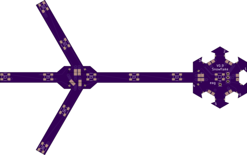
Which looks pretty nice. 9 LEDs on each arm plus one on the hub gives me 55 LEDs per snowflake.

Given the size of the scrunched together version, I think I can get the boards for 8 full snowflakes made and delivered in 12 days for around $80, which is pretty good.

The downside of this approach is that you spend a lot of time on the pc design, but I’d rather be doing that then spending days straining my eyes and back hand-soldering.

Now the big question is, “how lucky do I feel?” Do I order a whole run at once, or do I order one and verify that it works before ordering the other 7?


The DeWaltCast – Portable Chromecast Audio

I have recently updated my custom late 1990s multi-room music system to the 2010s with the installation of a Chromecast audio in my main equipment system. It is exactly what it should be; easy to use, easy to understand, and cheap.

But I was noticing recently that while it works fine when I’m in our upstairs kitchen/dining/living room area, I don’t have the option elsewhere. What I really wanted was something I could take out to the back patio for a bit of background music. I could have bought any of a number of small chromecast audio speakers, but they all required AC power, and in my stupidity I did not add a convenient outlet near my patio when I redid the basement.

I did some research, but I couldn’t find what I wanted, which was a system that would run either on battery or AC and didn’t have rechargeable batteries. I did some searching and researching, thinking about how I might buy a small boombox system, but the ones I found all used disposable batteries. Then I finally remembered that I already own the basis of such a system.

A DeWalt DC011 Jobsite radio. It is rugged, has an aux input (and a charming CD case on one side), but the really nice part is that you can plug a DeWalt battery pack into the back and not only will it use the battery pack to play the radio, it will also charge it whenever you plug the radio into an AC outlet. And I just happen to have a couple of 9.6 volt packs from a DeWalt drill that I recently deprecated in favor of a nice brushless Makita that I picked up. My radio is much, much dustier than the picture but still works okay, except that the optical encoder for tuning doesn’t really work.

The sound is okay, and I’m not looking for high-fi for this application, so that is fine.

This should be a very simple project; I just need a source of 5 volts to run the chromecast and a place to put it.

Nicely, the front is held on with 8 screws on the front and 2 on the rear, and then it just pops off. I expected it to be cheaply made, but the design is really pretty nice; instead of soldered wires between the boards there are real connectors. The only thing I find curious is that the battery charger is a hefty 4″x5″x1.5″ fully enclosed metal box at the bottom of the case, which explains a bit why the radio is so heavy.

A little bit of snooping has me a bit confused; there are nice red and black wires from the battery to the main board, but where I would expect a power cable to run to the radio, I see a 5-conductor ribbon cable instead.

image

I pull the power supply board and start tracing the back.

image

The filter capacitor is very obvious, and it turn out the the 5-conductor ribbon cable *is* the power supply cable; 3 conductors for positive and 2 for negative. A quick check with the meter shows that there is is no power across the filter capacitor, which makes no sense at all.

I look a bit closer, and realize that the whole board has a nice clear conformal coating on it, another sign of the build quality. I scrape it off the leads of the filter capacitor, put my meter on it, and find about 10 volts when on battery power and 14 volts when running on AC. That is a goodly amount of voltage.  I make a little power take-off harness and solder it to the terminals of the filter capacitor, and then reinstall the boards back in.

To get to 5 volts, I go searching. I want a buck converter that gives me 5 volts. The internets say I need around 250 mA, which pretty much any converter will give. There are hundreds of choices, but I settle on one from Xiny:

Like pretty much all of these, it’s made in China, but it appears to have reasonable build quality. I will just need to attach the wires, plug in the USB cable to the chromecast, and then run the audio to the aux.

While waiting for the buck converter, I hook up the Chromecast. I pull the aux jack out of the mount, plug in the cable, and temporarily plug the USB cable into power from the supplied wall wart. It fires up and starts working correctly. I hot glue it to the side of the case, and start to lay out the cables the way I want them…

image

Power

With that all sorted, all that is left was to hook up the power and close up the box.

image

I attached the incoming power to the screw terminal block on the left, tested that it really was giving me the 5V that I expected, and then plugged in the USB cord.

Finally, I tucked the power converter into a spot in the case and glued it in:

image

I plugged in the front panel & speakers, put it on the box, powered everything up, and started ‘casting to it. And sound came out the speakers.

*Most* of the sound was the sound of music. But there was a background of sound that was there even when the music was not playing. It was motorboating. There was a popping at about 8 Hz that would go for about a second, then stop for a few seconds, and then repeat.

Maybe it was the power, maybe it was the radio section of the radio interfering with the comcast. It would have been really smart of me to test all of this before I hot-glued it all into the case, but I pulled it all out and started eliminating causes. It is not the location of the chromecast or the short cable that hooks to the aux jack. It is not a ground loop. It pretty much has to be the 5v dc-dc converter.

I tried the usual hacky things. Capacitance on the unregulated input did nothing. Capacitance on the 5v output did nothing (well, it popped when I hooked it up, but nothing else). I put a scope on it, and could see the pulse train from the 5V output.

This was not entirely unexpected; one of the great things about our world is that there are lots of cheap components out there, but unfortunately this is also one of the problems.

I let it sit for a day, and then decided to try hooking the input to the battery instead of the power supply output to see if that made a difference. And the noise went away.

Unfortunately, the reason it went away was that instead of hooking the battery voltage – nominally 9 volts – to the input of the converter, I hooked it to the *output* of the converter, and pretty much immediately fried it. Worse, I had the chromecast plugged in at that point – because stupid – so I toasted the chromecast as well. I may try to pop it open and see if I can salvage it later; it seems to be cycling power on and off rather than just being dead.

Which led me to ordering another chromecast, and a different converter board. This time I got smart and found a board that people had been using to run a chromecast in their car.

image

In typical “explosion of search terms” fashion, this is the:

Yeeco DC-DC Buck Voltage Converter 10-24V 12V to 5V 1.5A Step-down Volt Transformer Stabilizer Voltage Regulator Module Vehicle Car Isolated Power Supply Switch Inverter Board with 5V USB Charger

The cool part of this device is that it’s actually an isolated design, which means there is no ground-to-ground connection between input and output.

In due time, the Yeeco showed – along with the new Chromecast audio – and I hooked everything up, and it worked very nicely. The components were stuffed in the case:

image

Then the case was closed up, and I was finished.

When in operation, the source electronics are silent – or at least more silent than the electronics on the amplifier. When you first turn it on, there is a short bit of noise as the Chromecast audio wakes up, which I’m calling a feature rather than a problem.

So, there you have it; for about $50 you can add ‘castability to an old boombox. Or, you can add another $40 if you don’t pick the right components and hook up the wires incorrectly.


Advanced Garage Lighting

I’ve had a project floating around in my head for a number of years…

We have a two-car garage with a nice white door that faces the street. I would like to use it as a canvas for something more interesting. My first thought was to build/buy/adapt a laser projector, and while I think that would be a fun project, it would unfortunately involve aiming laser light back towards the garage, which isn’t really the safest thing in the world. I’d also need to put the projector out in the rain someplace, so despite the whole “pew pew” lasers thing, I shelved it.

I’d also considered using some addressable LEDs, but for the first ones were pretty pricey, and I hadn’t figured out how I wanted to control them.

Recently, the project jelled (gelled?), and here’s the plan:

  • A 5 meter (2.73 fathom) strip of addressable WS2812 RGB LEDs, with 60 LEDs/meter so a total of 300 individual LEDs. This will be mounted under the front eave of the garage facing down and back towards the house. I chose these because they are the cheapest decent addressable LEDs available and they are fairly ubiquitous, which means you can find libraries to drive them for most microcontrollers. Which is good, because they have strange timing requirements.

  • A 20 Amp 5 Volt power supply. At full brightness each LED takes about 60 mA, and 0.06 * 300 = 18, which give me a bit of headroom. That’s about 90 watts to the LEDs, and these are pretty efficient, so yeah, that’s a lot of light. I had considered going with the strips that have 144 LEDs/meter, but they are a lot pricier and those would require 0.06 * 144 * 5 = 44 amps of power, which makes it less like a lighting project and more like a welding one.

  • A ESP8266 wireless microcontroller. These are really hard to beat; you get a microcontroller with a decent number of inputs and a full 802.11 wireless stack; it can function either as a wireless client that hooks up to your house system, or it can function as a hotspot on its own. And it’s cheap. I went with the Adafruit Huzzah because it comes on a nice board that can be driven by 5 volts, and because Adafruit doesn’t sell cheap stuff that breaks. And it’s still less than $10. Oh, and it uses the Arduino IDE.

  • A light sensor, so that I can use this as general lighting during the night. Sensor TBD.

  • A passive infrared sensor, so I can ramp the LEDs up to full brightness when somebody shows up. Sensor TBD.

The hardware part is straightforward; it will just be a matter of getting all the parts and hooking them up. I haven’t settled on my mounting approach for the strip, but I think it will probably be 3/4″ electrical conduit, as it is very straight, very rigid, cheap, and has decent ways to mount it to walls. That also lets me twist it around to adjust the light.

As for the software, that gets a little more interesting. The ESP will serve up a web page where you can choose your lighting scheme (all on, specific colors, a rainbox effect, etc.), and I’m planning on coding that directly in HTML since I didn’t like any of the libraries that I found. For the LEDs, I’m taking a different approach.

The existing libraries are written to run on Arduinos, which have very little memory, so you need to be very small and optimal. That leads to code that looks like this:


// Input a value 0 to 255 to get a color value.
// The colours are a transition r – g – b – back to r.
static uint32_t Wheel(Adafruit_NeoPixel& strip, byte WheelPos) {
   WheelPos = 255 – WheelPos;
   if(WheelPos < 85) {
     return strip.Color(255 – WheelPos * 3, 0, WheelPos * 3);
   }
   if(WheelPos < 170) {
     WheelPos -= 85;
     return strip.Color(0, WheelPos * 3, 255 – WheelPos * 3);
   }
   WheelPos -= 170;
   return strip.Color(WheelPos * 3, 255 – WheelPos * 3, 0);
}


static void Rainbow(Adafruit_NeoPixel& strip, uint8_t wait) {
   uint16_t i, j;


  for(j=0; j<256; j++) {
     for(i=0; i<strip.numPixels(); i++) {
       strip.setPixelColor(i, Wheel(strip, (i+j) & 255));
     }
     strip.show();
     delay(wait);
   }

Honestly, that is just awful; the animation is written right at the metal, and this approach doesn’t integrate well into the ESP because the web server can’t handle any requests while we are stuck in one of these loops. Luckily, the ESP has a lot more memory than the Arduino, and I can afford to spend that on some much-needed software abstractions. So, using the skills I apply at work when I’m writing C# I asked myself, “Self, what sort of library would I build if I had a bit of memory to spare?”. And this is what I came up with:

A Chunk is a series of RGB pixels that acts as a pixel source. Let’s assume that it has three pixels and is set to “Red Green Blue”.

A Mapper knows how to map a chunk onto the RGB strip. It is pretty simple; it just does the following:

for (int i = 0; I < strip.numPixels(); i++)
{
    strip.setPixel(i, chunk.getNextPixel);
}

The Mapper maps the chunk onto the strip until the end of the strip, so if our strip had 9 pixels, it would end up with “Red Green Blue Red Green Blue Red Green Blue”.

That gives me a simple static mapping, but chunk has one more feature; you can set the offset at which it will start sourcing pixels. So, if I write something like:

for (int offset = 0; offset < chunk.numPixels(); offset++)
{
    chunk.setOffset(offset);
    mapper.renderAndShow(chunk);
}

That gives me a chaser feature; every time through the loop, the chunk shifts one spot to the right, and the chunk wraps around.

I can also use this with chunks that are larger than the strip, and animate the offset back and forth to control the portion of the chunk that is shown.

The Blender class is used to create a chunk that blends two colors together; pass it the first color, the second color, and the number of steps for the blend, and it generates a chunk that implements the blend.

The following code generates a 180-pixel blend across 6 colors:

RGBColor red(255, 0, 0);
RGBColor yellow(255, 255, 0);
RGBColor green(0, 255, 0);
RGBColor cyan(0, 255, 255);
RGBColor blue(0, 0, 255);
RGBColor magenta(255, 0, 255);


Blender blender(180);
blender.addBlend(red, yellow, 30);
blender.addBlend(yellow, green, 30);
blender.addBlend(green, cyan, 30);
blender.addBlend(cyan, blue, 30);
blender.addBlend(blue, magenta, 30);
blender.addBlend(magenta, red, 30);


pChunk = blender.getChunk();

It is much much much easier to understand than the code I started with, and very easy to modify.

And finally, there is an Animator class that makes it easy to drive all of these from the loop() method. Give it a minimum and maximum offset, how often to modify the offset (so you can do slow animations), and the increment to add to the offset, and then just call run() every loop and it will handle the animation for you.

I’m pretty pleased with the current implementation, but it’s not quite good enough to easily implement a Larson Scanner, which is a definite requirement. I think I can do it with two chunks that are a lot bigger than the strip, but it would be inefficient. Perhaps if the chunks were sparse, with blank spaces at each end.


A pretty good twilight zone topper

Twilight Zone, being one of the top pinball machines with collectors and having a very good theme, has led to it being heavily customized, some of them being functional, but most just being ornamental, to make the machine more fun.

One of the cooler ones was done by a guy who took a small hallmark ornament that looked like a TV, put a small LCD display in it, and then used it to display pictures from the TV series while you played. It’s tiny (maybe 1.5”), and it fits inside of the game. And then somebody else did one that showed video.

I was thinking that it would be cool to do something that was game controlled, which is the whole reason I built the WPC pinball lamp decoder. And, instead of making it a small one that would go on the playfield, I decided to make it slightly larger and make it as a topper.

A topper is simply something ornamental that goes on top of your pinball machine. They are almost always lighted in some way, and, with a few exceptions, not controlled by the machine.

Mine would be. Twilight Zone has a bunch of different modes, and my plan is to detect those modes (and other events) by decoding the light state, and use that to play *appropriate* clips on the topper.

I needed a good enclosure. And, thanks to Ebay, it was simple to procure:

This is an early Sony 5” TV, and it was a bit of a design coup for Sony; nobody was doing TVs this small at the time. I toyed with the idea of just using it as a display, but then I took a look inside:

That is one of 3 circuit boards. These TVs have a reputation for being very hard to work on, and I don’t what that sort of project, so we are going to use it as an attractive case instead…

I plan on using as many of the controls as possible; at least the on/off switch and the volume knob.

For a display, I need a small LCD. I found one that is designed for a rear-view camera. Here’s a test-fitting in the case:

Fits but barely on width, but the height is less than I would like (the display isn’t really 4:3). Hmm. If I put it behind the original CRT protector…

That will likely work better. Assuming I stay with this display (and I think it’s the biggest one that will fit without hacking out the control section on the right), I will laser-cut an oval trim plate out of black acrylic that will cover the gaps. I’ll also modify the lens to get the display more forward.

and one more photo of the display working…


A bit about pinball

You may or may not know that I’m a pinball afficianado. Yes, yes, “ever since I was a young boy, I played the silver ball…”

During the arcade boom of the early 1980s, arcades were everywhere, and while they generally focused on video games, there were always a few pins. I spent lots of time and money on both, but pinball had more of a fascination, for three very important reasons:

  1. If you are decent on one pinball machine, you are decent on all of them. This is very much not the case on arcade machines; your skills on Defender help you when you play Tron, but you aren’t automatically decent.
  2. The physicality is much better. You get to shake the machine. No, you are *required* to subtly nudge and shake the machine while you play if you are going to be a good player. You work on your advanced moves. And you enter a society of players who know how to play the right way. It’s a bit of a craft.
  3. You can win free games. Plus, the difficulty level on a pin is mostly linear; yes, it becomes a *little* harder on most games as your points go up, but it’s not a lot harder. What that means is that once you are good, it becomes easier to get high scores. And, every once in a while, probability and skill will align, you will walk into an arcade, put one quarter into the pin, and play for half an hour, with the game knocking to announce your skill when you win a free game. And then, after that time, you will turn to the 12-year-old kid who has been watching you play and say, “I have to leave. Do you want my games?”

So, anyway, I played a bunch of pinball in my young days, but it tapered off when I got older because pins and vids became much harder to find. You could find them in bars, but I don’t do well with cigarette smoke, so I didn’t play as much as I used to.

Then, sometime in my 30s, I realized that a) it was possible to own a pinball machine, and b) I could afford to do so. So, I craftily bought a Williams Bad Cats:

The reason it was crafty is that I bought it because a) it was a relatively inexpensive machine (I think I paid $800 + shipping), and b) it was my wife’s favorite machine.

I reconditioned it, played it for a while, but there was still a problem.

I wanted a Twilight Zone…

Twilight zone is complex machine. A really complex machine, with ramps, ramp diverters, a working pinball machine, a magnetic mini-playfield, and a impressively complex ruleset. Oh, and it has a lightweight ceramic “powerball” that moves really fast, two different 3-ball multiballs, and – if you are worthy – “Lost in the Zone”, a 6-ball timed multiball mode.

In fact, it was so complex that it didn’t really do well commercially; novice players found it too challenging and confusing.

But skilled players loved it, and made it a hot commodity in the resale market. I was lucky/smart enough to buy mine around 10 years ago, when machines are a bit more plentiful, and paid around $3500 + shipping to get it. These days you will probably play twice that.


Pinball Lamp Matrix Decoding–Completed board

I got the boards back from OSHPark a while back, and got around to populating them. Though I have access to a real reflow oven, I’ve done boards like this with the heat gun method in the past, so I got out the solder paste, put it on the solder pads, put on the shift registers, and then went out to the garage.

I use an old license plate as a board holder, so the board goes on that.

Real reflow ovens use a time/temperature calibrated curve.

Basically, there’s a long soaking stage to gradually bring all the parts up to temp, a ramp up until the solder melts, and then a cooling-down period. I attempt to duplicate this with the heat gun, though it’s really not very precise.

The hard part with the heat gun is keeping it at a distance where it does not blow the parts around on the board; as the board heats up the flux will start to flow and the chips want to move. A little repositioning with a toothpick fixes that. You keep heating until you see the solder reflow, make sure it’s reflowed around all the parts, and then remove the heat.

And you get this:

The 34-pin connector and the two test point connections were hand soldered. I do need to test the board itself and then hook it up to the pin and see if it works.


Pinball Lamp Matrix Decoding–Board design

Since I got the prototype working, I now need to convert it to something real. In the past, I’ve typically done this by hand on perfboard. This takes a lot of time to do, and the results are functional but not that great.

This time I’ve decided to go direct to a PC board, so I fired up Eagle. I think this is my third design with it, so I’m reasonably decent at it, but I’ve forgotten how strange CAD user interfaces always are; they were developed before much was known about how to build good graphical user interfaces, they are all different, and they don’t follow UI guidelines. Oh, and they tend to have some weird metaphors as well, and there is no equivalent of github or stackexchange for them.

I installed the Adafruit library by downloading it, unzipping it, copying it to a directory and then adding that directory to the library path (nuget, anybody?) so that I could start with their arduino shield outline. It has all the pins on it. I then searched for the 74HC589 shift registers. No luck, so I stated to design my own, went back, did some more browsing, and found the 74xx589 SOIC-16 design, so I could use that. I need a 34-pix (2×17) connector header; I found a 2×20 and modified it. Then, I built a new version with named pins to make it easier to wire things up.

At that point, I started the wiring. A bunch of work, an “invoke” to get the Vcc and Gnd to show on the shift registers (once again, CAD weirdness), and I ended up with the following schematic.

Basically, we have the 8 data lines and two strobe lines going from the connector to the shift registers, the two strobes heading to Arduino (pins 2 and 3 because they are the ones that support interrupts), and then a bunch of lines between the Arduino and the shift registers. Prettiness isn’t important here, though it needs to be neat enough to know whether it’s correct or not.

I also threw on two test point headers; one for ground and one connected to pin 4. I often use a pin to write debug information for an oscilliscope, so the headers give me an easy way to hook that up. I run the schematic rules engine, fix a few things, and the schematic is done.

Once you have the schematic in good shape, you can create a board to implement it. I should have taken a snapshot at the beginning because it was quite the mess; there are 8 data lines that need to make it to both shift registers, 3 shared lines from the arduino to teach shift register, plus Vcc & Gnd. Lots of overlap potential.

I like doing board layout; it starts out looking pretty hopeless, and you play a little, it gets better, and then finally it sort of jells and then you are doing cleanup. Here’s the board layout I ended up with:

Lots of left-right rights to route all the signals that go to both chips. I’m pretty happy with this layout; it’s reasonably ordered, and you can tell where things go. I run one line right under the pins of the shift registers; something that I couldn’t do if they were through-hole chips.

Two things I could have done; I could have switched pins 2 and 3, and I could have pulled one of the signals off of pin 11 and used pin 7 instead. I didn’t because I would need to redo the software; a small thing, but the current layout works fine.

Once the layout is done, I run through the design rules. It’s really easy to end up with weird stuff; multiple vias slightly overlapping, traces that don’t quite go to pins, that sort of thing. I’m planning on fabbing the board at OSHPark.com, and I remember that they have their own design rules, so I download them and run them.

Then the last task is to shrink the design down from full shield size to something smaller to save a bit of money. Oh, and I add a label or two. Upload it to OSHPark, and they tell me $20 for 3 boards. Pretty good.


Decoding Pinball Bus Signals Part 4

After spending a few weeks working on the software, it’s time to get back to the hardware. My first task is to hook up the arduino and see if I can reliably trigger off the interrupts.

The answer to that question is yes; setting the trigger on “FALLING” works reliably. But I came across the following behavior that is a big puzzling:

These are the row and column strobes. On the left, you can see the top strobe happens first, and then the bottom strobe. If I zoom in, I can see that they occur when data is present on the bus (bus signals not shown). Just as it should be.

But what is going on with the signals on the right? Here’s a bigger picture:

This is weird; first we see a column/row strobe with some crappy looking bus data, and then a row/column strobe with some good looking bus data. This would seem to indicate that part of the time, the CPU sends data and then sends different data soon after, and other times it just sends the data. The hardware in the machine won’t care; the time that the first data is present is so short that it should not affect the behavior of the lights in a noticeable way.

But is this what is really going on, or is it a glitch in my logic analyzer? Time to find out…

BTW, the big square wave in the middle is an output from the Arduino. An interrupt service routine is hooked up to the bottom signal on the trace, and the lag between the negative edge on the strobe and the positive edge on the arduino trace is the time it takes the interrupt to happen + the time it takes to turn on a pin. So, it appear the decision not to do this purely in software on the arduino is a good one.

To figure out what is going on, I wrote an arduino program:

void setup() {
  pinMode(0, INPUT);
  pinMode(1, INPUT);
  
  attachInterrupt(0, rowDataHandler, FALLING);      // pin 2
  attachInterrupt(1, columnDataHandler, FALLING);   // pin 3
 
  Serial.begin(9600);
}

unsigned long startTime = 0;
const int ArraySize = 128;
unsigned long rowTimes[ArraySize];
unsigned long columnTimes[ArraySize];
int rowIndex = 0;
int columnIndex = 0;

void rowDataHandler()
{
  digitalWrite(8, HIGH);
  if (rowIndex < ArraySize)
  {
    rowTimes[rowIndex] = micros();
    rowIndex++;
  }
  digitalWrite(8, LOW);
}

void columnDataHandler()
{
  digitalWrite(9, LOW);
  if (columnIndex < ArraySize)
  {
    columnTimes[columnIndex] = micros();
    columnIndex++;
  }
  digitalWrite(9, LOW);
}

// the loop function runs over and over again forever
void loop() {
 
  while (rowIndex < ArraySize && columnIndex < ArraySize)
  {
    Serial.print(".");
  }
  Serial.println();

  Serial.println("Times");
  for (int i = 0; i < ArraySize; i++)
  {
    Serial.print(rowTimes[i] – startTime);
    Serial.print(",");
    Serial.println(columnTimes[i] – startTime);
  }

  Serial.println();

  startTime = micros();
  rowIndex = 0;
  columnIndex = 0;
}

Basically, it sets up interrupt handlers for both row and column strobes and then starts saving the time when the interrupt occurs. When it has collected 128 of each, it stops collecting them, and the main loop sends them out over the serial port. Then the process repeats itself.

I took the data and pulled it into Excel for analysis. This is the delta time between interrupts, all times are in microseconds.

Row Delta Col Delta
   
2064 2112
44 44
1992 1992
44 44
2048 2044
44 44
1952 1956
44 44
2000 2000
44 44
2008 2008
44 44
2000 1996
44 44
1996 2000
44 44
2000 1956
2048 2048
2056 2056
2052 2096
44 44
1988 1984
44 44
2008 2008
44 44
1996 1996
44 44
2000 2000
44 44
2000 2004

There are times with a double interrupt, and other times that only have a single. Sometimes the row interrupt comes first, sometimes the column one comes. The period is right around 2 mS, so the frequency is pretty close to 500 Hz; exactly what I had measured before. The time period between the first one and the second is either 44 or 48 uS; I think the difference depends on the ordering.

The ratio of the two time periods is 44/2000, or just about 2%. Based on my extensive experience dimming lights by microcontroller, I can tell you that 2% isn’t really a noticeable difference in how a light looks; you *might* be able to detect the difference between 98% and 100% brightness in a controlled setting, but it would be hard to do. I’m confident that you can’t tell the difference between 0% and 2%, because on a incandescent light, 2% is just off.

I did a little graph in Excel that looked pretty much exactly like the logic analyzer image, so I won’t share it here.


How to deal with this? Well, I think it will actually turn out to be pretty simple. Instead of doing work directly off of the row or column interrupts, I will set up a short timer interrupt (let’s say 100 uS or so) whenever the row/column interrupt fires. That will be updated by any new strobes that occur before the timer expires, so the effect will be that the timer interrupt will be serviced a short time after the last row/column strobe.