
One of the realities of doing CAD work is that the real world sometimes intrudes…
Your laser cutter – for example – is limited to cutting a given size of material, and only in one plane. And it isn’t a perfectly thin cut, there is a little width to the laser beam.
For router-based machining, one of the problems is that the cutter is round, and often the cuts you would like to make are square. Here’s an example:

The part on the left is what you designed, and the part on the right is what you got when you cut it. There are a few approaches to deal with this; you can cut the corners out with a knife or saw, you can just pound the parts together and hope the material yields, or you can change your design so that the corners are cut out. It looks like this:
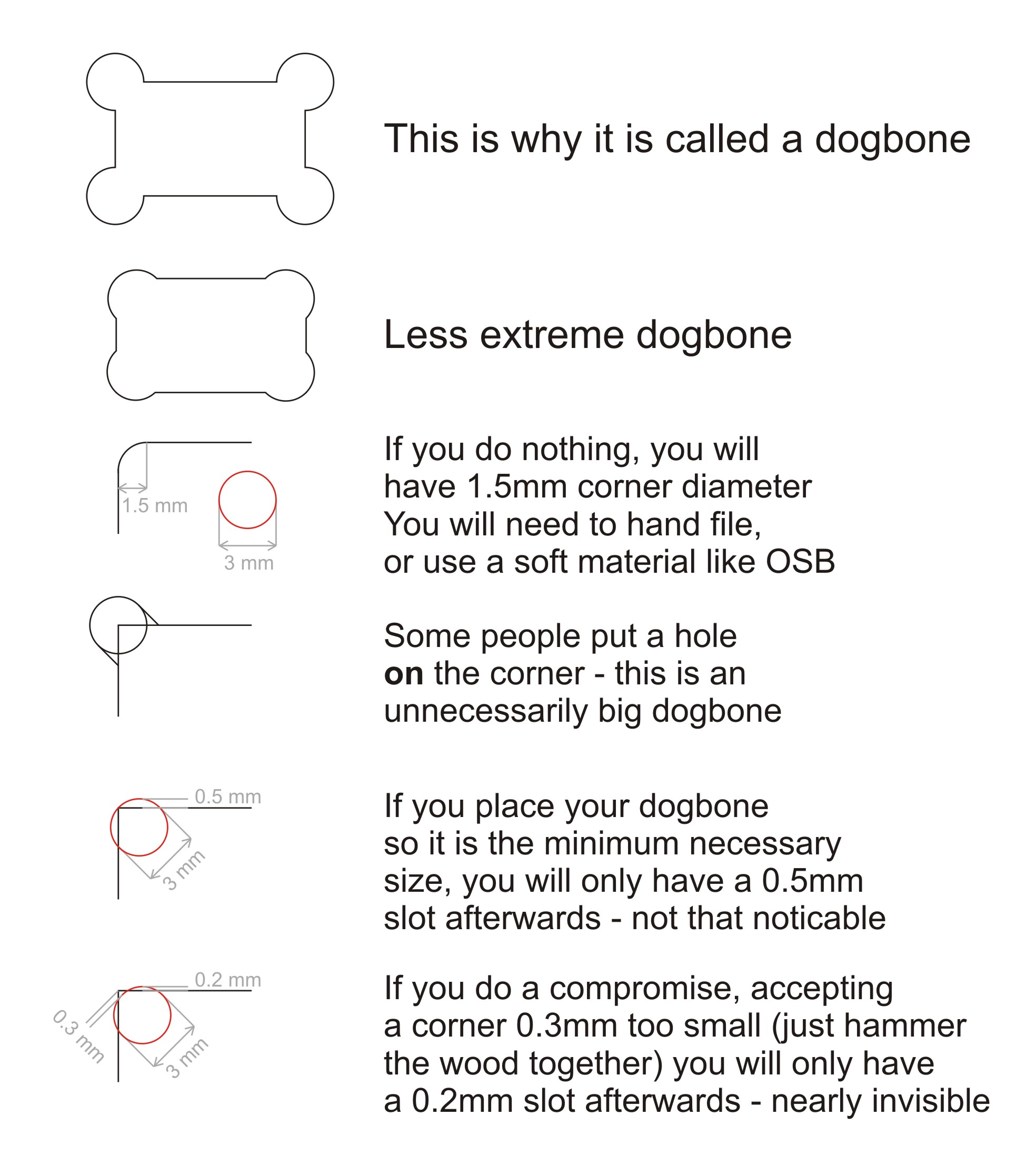
Hence the name “dog bone”. With the Shaper, there are a few ways to do this; you can either modify your design to include the dog bones, or you can do them on the tool, one at a time, kind of by hand. Since there are hundreds in this design, doing them on the tool did not seem very exciting.
There is an add-in for Fusion 360 that does dog bones, so I installed it and tried it on a few designs. Like lots of freeware, it’s a bit challenging; you either have to pick every corner where you want the dog bone, or you can let it pick the corners that need to be modified but this only works if the corners are vertical.
Oh, and it takes a long time. A *long* time. Like 5 minutes for a panel with just a few cuts if you mark them by hand, or 20+ minutes for one with lots of holes (19) where it figures out which corners to modify. This is made much more annoying because Fusion 360 does something that I thought wasn’t supposed to be allowed under Windows UI guidelines any more; the status bar that it shows brings the window to the foreground and selects it. Since this is happening about every second, you can’t do anything else on your computer while the dog-boneification process is underway. Which kindof gets in the way of making good progress, since you need to go and do something else.
About this time I needed to get some wood for the shelf, and I needed to know how much and how I would arrange it the cut pieces on the board. I found this tutorial to be very useful in understanding how to do that, and ended up with a nice layout on a 24” x 48” sheet that used a bit more more than half of the space.
Went to add the dogbones by selecting all 13 pieces in the and kicking off the add-in. An hour later it was still running. Two hours later is was still running, much more slowly. Left it overnight and came back to the autodesk crash dialog.
About this time I was really thinking of just using the Glowforge and forgetting about dogbones, but the whole point was to use the shaper, so I pressed on.
Went out for lunch, picked up some stock (birch plywood that was 4.7mm thick), rolled back to my 3-d layout, set the thickness of the stock, and went through and did each of the dogbones by hand-selecting each corner. After that was done, I ran the Fusion 360 plug-in for the Shaper Origin, which generated SVG files that I uploaded to their website (you can use a USB key if you’d rather). I was going to do the bottom part of the design; the last wide shelf and then the pieces that hang the hub underneath that, four pieces in total.

At some point, Fusion lost the material selection for the one piece, and I was too lazy to fix it.

Here is the setup. Sitting on the router table portion of my BT3000 table saw, I have an extra ikea shelf (melamine and very flat), a sacrificial piece of MDF on top of that (you need to cut just through the material), and then the birch plywood on top (that piece was about $8). Across the wood you can see the “shaper tape”; this is how the vision system on the router knows where it is. The basic process to cut is:
- Move the router around so that it locates all of the domino-shaped shapes on the shaper tape.
- Load a design (in this case, from the online pieces I uploaded)
- Set the cut parameters (the size of the cutter you have in the router (1/8” in this case), how deep you want to cut on this pass (I did two passes, one at 0.125” and one at 0.2”)
- Do a “z – touch” so that the router knows where the top of the material is and can therefore judge depth.
- Move the router so that the line you want to cut is inside the circle.
- Turn the router on (using the physical switch on the head)
- Press the cut button (green button on the right handle), and wait for the bit to plunge into the work.
- Navigate the router around the cut.
- Press the retract button (orange button on the left handle), and wait for it to retract.
At that point, you can move to another cut that needs to be made or change parameters and recut the same line (deeper, for example).
This worked really well, except for two issues. The first was that on my second cut, something went wrong, and on the cut, the router plunged the bit as deep as it could and then the software crashed (you can see the burned hole near the bottom of the workpiece). I had to turn off the router, pull it carefully out, and cycle the power on the shaper to get back. The second was my fault; I cut all the way through an outline before forgetting that the piece I cut had a cutout. Oh, and the software crashed again when it was just sitting there; the image on the display is a static one before I moved it to make the picture nicer.
And the result is…


What do we see? Well, the first thing you’ll notice is that there is a lot of fuzziness on some of the cuts. The shaper uses an upcut bit, so that’s pretty common. The fix is to do the first cut at a bit of an offset back from the line and then do the final cut without the offset. Overall, the lines look really straight, which is remarkable given that a human is moving the router around.
What else do we see? Well, the joints don’t look very good, and there is a distinct lack of dogbones on them.
It turns out that I outsmarted myself. One of the tricks with dogbones in wood is to set the cutter size slightly smaller than the actual size of the cutter; that makes the dogbone a bit smaller but it still works since the wood has a little give to it. But… the Shaper knows the size of the cut you are asking it to do and the size of the cutter, so it just avoids cutting the dogbone path. I cut them by hand with a utility knife, but I was short of time so this is the result I got.
Finally, a couple of action shots with the hub in place:


Up next is to redo the dogbones for the remaining pieces *again*, and the cut them using the offset to see if I can get nicer joints.
So, what do you think ?