I’m starting a new decorations project that will involve a fair number of standard LEDs, but not addressable ones. I have a few different use scenarios:
- Plug into a standard USB power supply.
- Power directly with 120 VAC.
- Power either with 5V or 12V and have an easily way to control brightness…
The first two are just wiring, but the third needs something more. My target market is quite used to using WS2812 addressable LEDs, so I’m going to build something that works in that environment.
Quick requirements list:
- Runs on 5V or 12V.
- Uses WS2812 protocol.
- Can drive significant loads (at least 10 amps).
- Small and cheap
The second requirement is pretty simple; you can buy the WS2811, which works exactly the same way as the WS2812 lights but is in a separate package. And it very conveniently has a little internal power supply that can use 5V or 12V by changing the value of one resistor. Here’s a typical 5V circuit:
Looks very nice, and almost does what I want, except that it’s designed to only sink 18.5 mA, which is quite a bit less than my 10 amp goal. I don’t strictly have a use for 10 amps right now, but I will likely need at least 1 amp for some uses.
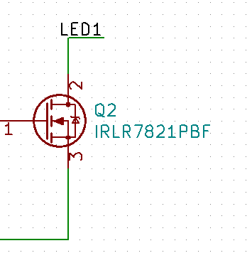
So, I’m going to lean on the IRLR7821PbF MOSFET that I used in my backyard controller, which it looks like I can get for about $0.14 each. It’s pretty easy to use:
I will just drive the gate of the MOSFET with the output of the WS2811, and when the MOSFET turns on, it will pull the LED1 line low, turning on the LED.
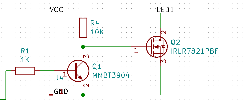
Except… the WS2811 outputs are active low, and the MOSFET in this arrangement is active high. So
We add an NPN transistor. If the input is low, the transistor is off and the gate on the MOSFET is pulled high by the 10K resistor. If the input is high, the transistor is on, the gate is pulled low, and the MOSFET is off.
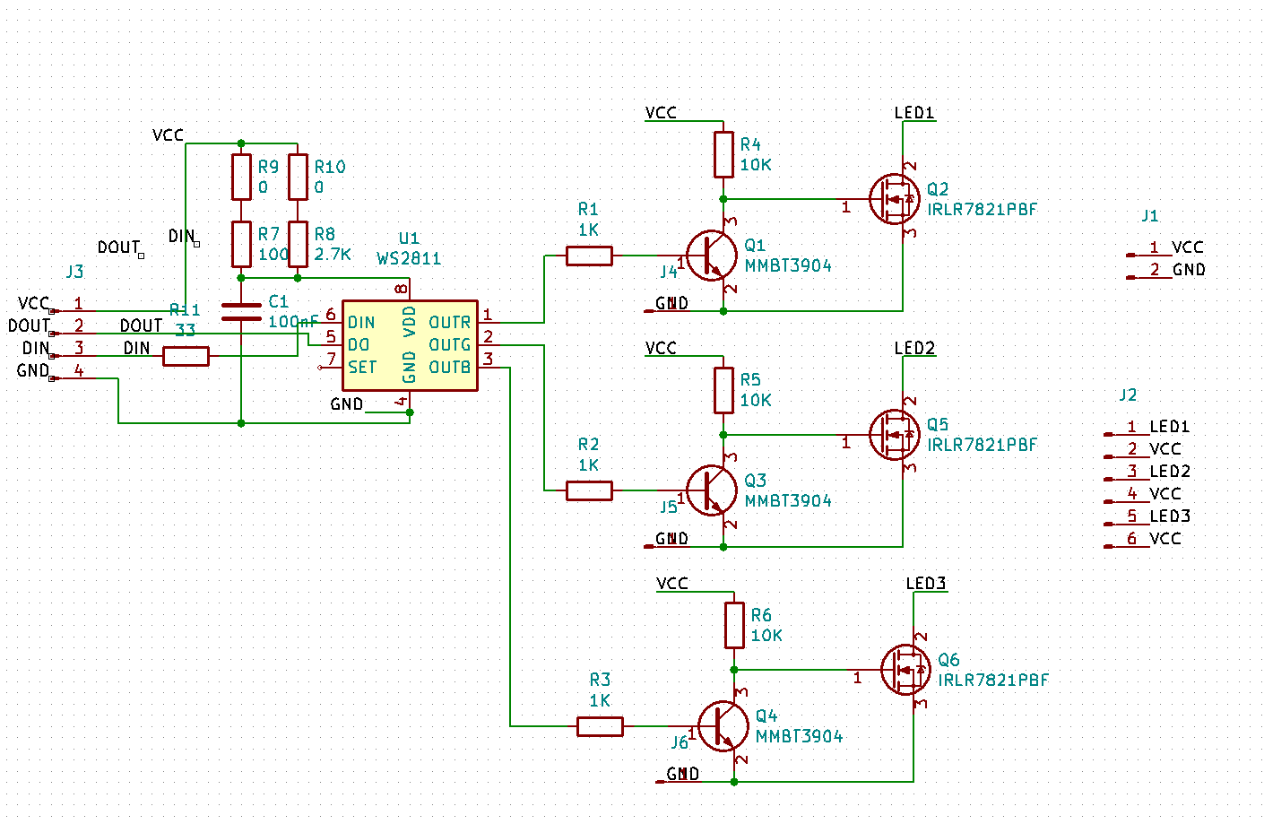
That will be duplicated for all three channels, and we end up with the following:
R9 and R10 are really just empty holes; you bridge R9 with wire if you want to use 5V and R10 if you want to use 12V.
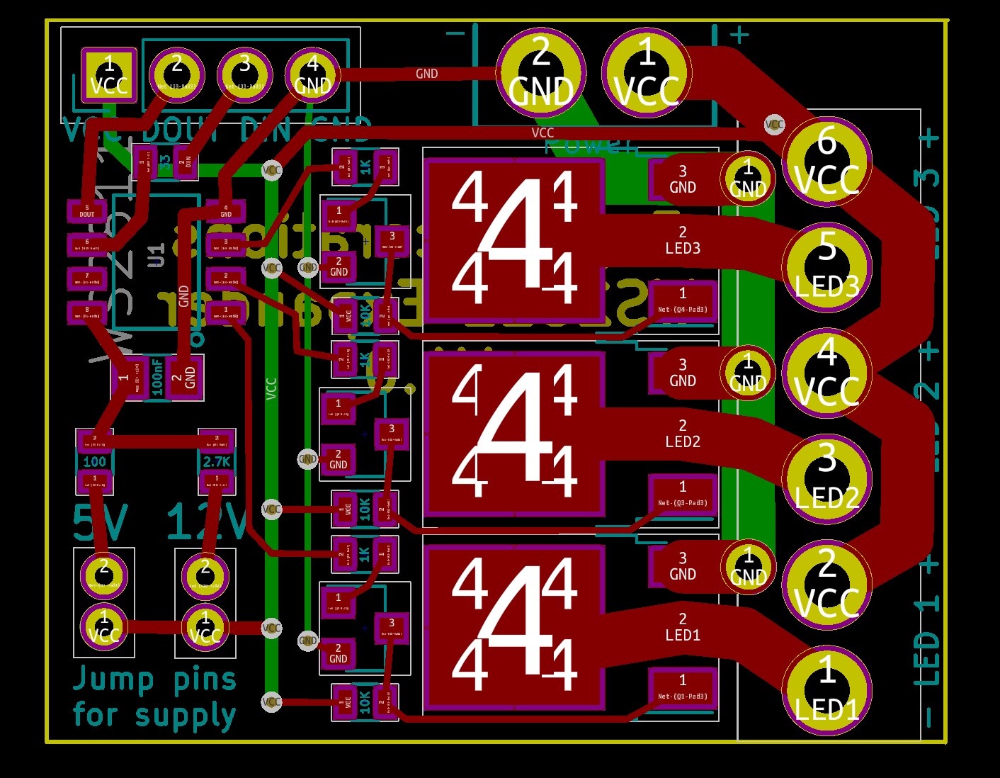
I unfortunately generally forget to take snapshots during PCB design, so here’s the V1 state:
The MOSFETs have lots of 4s on them – I don’t know why – and to the left are the bipolar transistors and the resistors required for that part of the circuit.
The power input holes and the LED holes are designed to use Molex KK 396 headers and connectors so you can either use those or hand wire.
The lower left shows the jumper locations to set voltage.
All resistors are 0603 sized; that makes them compact but still relatively easy to populate.
The only weirdness are the three through-holes next to the LED terminals. I need to tie that backside ground trace to the frontside MOSFET terminal, but I was having trouble fitting enough vias to carry the current. Instead, I just used the through holes, which will be filled with solder and therefore be able to carry plenty of current.
The board is about 40mm x 28mm in size. I might jump up to 0805 resistors to make it a little easier to fabricate.
Before I send it off to be fabricated, I need to have the transistors in hand so I can verify the layout works.


Hi,
So finally , did you manage to fabricate the final board, populate all components and given a run.
Please reply so that I can start work on your design
Sandeep
Yes, I talk about that in the later posts.
Hi,
It won’t work with the given schematic, you need a pullup resistor on the base of the transistors since the ws2811 won’t actively go high, only low is driven so when left floating the transistor will go off, fet will go on and that’s it. Put a 1k from pos to ws2811 outputs and you’re good to go.