Passport2Pain 2018

This is my third attempt at the “Idiot Level” Passport2Pain course, and my third completion (2013, 2016, and 2018). In 2016 I left my GPS at home and apparently didn’t bother to write anything up, so any comparisons will be to 2013.

My wife and I went over Friday afternoon to have dinner with and stay at the house of one of our ski instructor friends, who very conveniently lives 15 minutes from the starting line. I slept poorly as is my usual before big rides, but got up, skipped breakfast, and we headed over to the starting point.

After the usual wait and ride introduction (“In thinking about fundraisers, we had an idea. It wasn’t a *good* idea, but it was an idea…”), we queued up to start. They start with 4-5 riders every 30 seconds or slow to spread the riders out. Contrary to the pre-ride description, they made no effort to actually send out the idiot (80 mile) route riders first; I knew to line up near the front but I would have been upset if I had to wait 40 minutes to start. Considering the difference between the two routes is well over two hours, they need to do better at this.

We pedaled away from the start at Jensen Point, which is on this weird little spit. I started talking with a guy in a t shirt, jersey, and cutoffs; he had forgotten his clothes. He pulled ahead and took the first turn to exit the park area and immediately pancaked on this left side.

It had, you see, rained the night before and it was 57 degrees and cloudy. So there was still a bit of moisture on the road, and likely a bit of oily film.

He was fine and we rode off to start our quest, and I made a mental note not to ride too near to him – or any other riders – while the roads were wet.

I generally describe P2P as riding all the way around Vashon island and taking every road that goes down to the beach.

image

That is hyperbole. There are, in fact, numerous hills that will will not ride down, but we will ride down a large number; overall, there are 25 climbs on the ride, most of which are in the 200-300’ range, plus a bunch of small hills and rollers. If you are doing a ride like RAMROD, there are really only 3 hills (Paradise, Backbone ride, and Cayuse), and that’s how you track your progress. On P2P they do have checkpoints where you get your passport stamped, but there are 18 of them.

My approach is to just ride; I know what the parts are, and I know that I need to ride slow because the last set of hills is pretty bad.

So, we head off, do a short climb, and then descend down to the first real climb, which is a weird down and up. And quickly run into our first issues.

We roads and steep climbs do not mix. Going down you can just take it easy, and even with disc brakes I’m taking it easy on the still wet roads. The problem is when you start having to go up again. I can sit and ride up a 15% hill pretty easily and tough out a 20% hill, but it’s nice to be able to stand. Except if you do that, your rear wheel spins up. Which is bad. So, you just need to sit and suffer.

The first 5 stops go by pretty fast; slow and careful on the descent, and then doing my best on the climbs to stay smooth and keep calm. This part of the ride is the warmup, though it’s a little nuts that the warmup has 8 main climbs and 2500’ of up over the first 25 miles. We then have 5 miles with a climb or two, and then turn off onto Burma Road.

Burma is a mostly paved goatpath that rolls up down and around; they laid asphalt with doing as little grading as possible. Burma has one easy climb – say 13% or so – and then two hard climbs. They are aren’t very high, but they are well in excess of 20% (my GPS said 27 but I really don’t think they are quite that bad). The general way to attack Burma is to be able to ride slowly – say 3MPH – while standing, and if traffic permits, do a slight weave back and forth. It’s not categorically different than “The Widowmaker” in Sufferin’ Summits, and it’s quite a bit shorter, though it’s barely one lane wide.

That is what I did on two previous rides, but Burma is fully shaded and quite wet this year. After spinning the rear up despite being really gentle, I just ride slowly and muscle my way up. Not fun at all and I’m stressing my legs much more than I hoped, but it’s either that or just fall over (I don’t think I could unclip and stop), so I ride up both pitches apprehensively and then get to meet the devil.

Almost directly after, there’s another hill with a torn up descent at the bottom where you can barely stop and an ascent where you can’t stand, but that’s par for the course. Later this same hill has a solid 20% section, but luckily that pavement is dry and a real road so you can tack/paperboy back and forth and stand if you want to.

There’s one more loop down to the water, a spin along the main highway, and we hit the lunch stop.

I’ve been snacking a bit along the way; I have some nuts and I’m eating small amounts of carbs, and that’s working great except for 5 peanut M&Ms that give me a knot in the stomach.. At this point, I’m pretty tired and deciding whether to do the 55 mile or the 80. I eat the fillings of a very forgettable BLT and a bit of bread and then stop at the Thriftway for a Coke Zero but am stuck with a Diet Coke.

I mean, seriously, what are they thinking?

I text Kim to let her know where I am (she is doing a ride into the village for coffee) and tell her I’m 50/50 on which variant I will do and I’ll text her when I decide.

I roll out. There’s a small and ugly climb on the next section, but this one is dry and I’m feeling decent until my right hamstring starts to cramp near the top of the hill. I stop, dig some electrolyte capsules out of my pack, and wash them down. Then it’s off to Evil Twin #1 and #2. They really aren’t that bad and I’m climbing a bit better after food and Diet Coke. The second stop has chips and guac, and I have a few, heavy on the Guac.

And that’s all the hills on the 50 mile/6500’ route, so I need to make a decision. My toes and left shoulder hurt a little, but my legs are feeling okay, so I stop to text Kim and press on, onto Maury Island, and get ready to grit my teeth. Because as tough as the Burma Road section is, this section is a real bastard. It looks like it won’t be that bad – there are only 5 stops – but it’s a full 30 miles and over 3000’ of up.

We work our way through 14, and then descend down to 15. This has the added pain that as I near the stop, I ride by our friend’s house and out in front my Outback is parked, with a perfect bike-shaped space in the back, beckoning to me. I manage to avoid the temptation, but man, the hill out is a major bitch, and I’m tacking back and forth for all I am worth. And it’s not like I’m getting passed much, since all the fast people are in front those near me are bound together in a brotherhood and sisterhood of suffering and pain.

On the plus side, I’ve had no more cramping issues, so there is that.

Then there’s an ugly descent, and we ride into Dockton. We have three stops left, so three hills, right? How bad could that be?

I hate Dockton. We are down right at the water, but we climb 300’ up to the top of the island, and then we descend all the way to the water down yet another sketchy, wet, and slightly mossy road. For a measly stamp on our passports. Then we climb out that same damn hill, though the way from the water is worse.

And then – and this is the wonderfully terrible part of this ride – we do it again. Climb 200’ up into the hills, all the way down to the water, collect our penultimate stamp, and then it’s another 250’ climb back to where we started.

And the pain of Dockton is over. At this point I’m feeling pretty good; I *know* can finish the last hill, and then there are only a few rollers after that. I ride up a 150’ uncategorized hill – I mean really, it’s only a 7% and it feels very easy – in company with another rider, and I form a plan.

There is only one hill left and my legs feel like they have a little something left. So, we come to the last hill – 330’ of fun or so – and I start climbing hard, which is somewhere between 230 and 280 watts as the hill steepens and eases (my earlier target was <200 watts if I could). My data shows that I’m 43 seconds faster than my 2013 ascent – a full 9% faster. I get to the top, have a little bit of popcorn, and spin out to finish the ride.

The way back is about 4 miles with only a few rolling hills, so I push my speed up a bit. And then, finally, I finish, and get to have some well-earned barbecue with my spouse. It’s pretty good in the “Puget Sound Barbecue” category, but the brisket needed another couple hours in the smoker.

Analysis

Strava says I pulled 12 PRs on the route, and 9 of those were on hills. That makes me pretty happy, and I felt strong for most of the ride. It’s so much nicer and prettier than Sufferin’ summits.

Stats:

80.81 miles
7:11:46 riding time
9,949’ of up
11.2 mi/hr average

How does that compare to 2013? Well, in 2013 I rode 1.5 miles farther, which was probably due to more back-and-forth across the road, and finished in 7:13:27. My average speed then was 11.4 mil/hr, faster than this year, but my speed on descents was at least 25% slower than before because of the wetness.

2013’s ride was done on my Trek Madone, a fine bike for making speed but it was pretty harsh on the crappy Vashon roads. This year I was on my Roubaix with disc brakes, a frame tuned to soak up vibration, shocks in the seat and steering head, and 28mm tires at 80 psi. It was gloriously better; the stuff that really would have beat me up last year was still annoying but not too bad.

image


Sufferin’ Summits 2018 – Smoky summits with rain on the side…


Exposition

As some of you know, Sufferin’ Summits is a stupid idea I had 4 years ago that I’m still paying for 4 years later… It all started with a simple idea – could I create a ride like Ronde PDX – where “Ronde” means “A dance in which dancers move in a circle”, and PDX refers so a “Private Data Exchange”, a way of exchanging data without being burdened with all of the downsides of the public internet.

Where was I? Oh yeah, the ride. So, anyway, I came up with the outline for a ride, and it was pretty stupid. And then I went out and rode a bunch of hills and figured out a way to make it stupider. It is simply the hilliest ride that I could cram into 55 miles, something around 9000’ of up. And it turns out that it’s worse than Ronde PDX, though they do have a second day (okay, so, technically, there *is* a route for the second day of Sufferin’ Summits, but I am just not quite stupid enough to publish it, let alone ride it the day after).

For the first couple of years I did some light marketing of Sufferin’ Summits to the local community, but now I just kindof let it sit out there, the lesser-known, poorly behaved, and frankly less attractive cousin of Passport2Pain. I tell people that it’s because I want it to have that “underground” mystique, but the reality is that I’ve worked with people who organize big rides and I’m far too lazy to put in that much effort. So, it typically pulls in 20-30 people, and that’s just fine; I get to ride it with a few friends and look publicly stupid to the rest of the cycling population. Win win in my book. The ride is technically unsupported though my lovely wife has hosted a snax table at the halfway point the past two years.

I generally spend quite a bit of time in these hills on the Saturdays during the summer, and I felt pretty good about my fitness this year. But, there were two possible flies in the ointment, chinks in my armor, or bats in my belfry:

The first was that we had been treated to an extended run of “Wildfire Smoke”, and let me be clear that it was it was not the Tony-award-winning production that we had been promised. It was on hiatus Thursday night, but came back for an encore presentation the day of the ride. It was officially in the “unhealthy for sensitive groups” category, which – among other things – says that if you experience shortness of breath or unusual fatigue, you should contact your health provider.

I’m not quite sure how to apply that advice in practice, since “shortness of breath and unusual fatigue” bears an uncanny resemblance to the my written mission statement for the ride…

The secondary issue is that because of the crappy air quality, my training for the past few weeks has been a lot lighter than usual. I’m a fan of a nice taper in general, but two rides in two weeks is a bit extreme.

Anyway, that’s enough foreshadowing for now…

Friday night, we watched the Hawks extend their perfect preseason record, and then I headed to bed. That 5:30 AM alarm was going to come soon enough. And yet, it didn’t. Because I could not get to sleep, and 2 AM found me on the living room couch, reading (“Crash Test Girl” by Mythbusters alumnus Kari Byron is pretty good, and “Year of the Cow” (Stone) is a fun mix of history, science, and cookbook). So, anyway, I got off the couch at 5AM and then proceeded to not make my usual breakfast of bacon, eggs, and berries, because I typically do these rides (mostly) fasted. My food bag has one Honey Stinger “waffle” (mostly emergency carbs), a small bag of cheez-its, and a small bag of extra mixed nuts (that’s what you get if you take mixed nuts and add more nuts, right?). One water bottle has water, the second gets a serving of Biosteel hydration powder mixed into it, which I’ve been experimenting with for electrolytes recently. You know that it’s good because a) it has Calcareous Marine Algae and 2) the “mixed berry” flavor I have tastes remarkably like the cough syrup my parents gave me when I was a kid. On the way out I mix up two scoops of SuperStarch with half a scoop of endurox in a failed bid to make it more palatable; two scoops of highly educated cornstarch in a glass of water tastes exactly like what you think it does.

Oh, and I grab 12.5 macadamia nuts and eat them on the way out of the door because macadamia nuts.

The ride starts at a park in Issaquah, and I expect that the smoke is going to affect the turnout. We end up with 13 of us at the start, which is a few more than I expected. I ask how many people are doing the ride for the first time and then give a quick pre-ride briefing, which mostly consists of an assertion that while experience would lead one to expect that the first half of the ride is worse than the second half, experience would, in this case, be a poor guide.

Did I mention it was cold? Two years ago we started at 9 AM and it was 95 degrees when we finished, so the official (which only means “ride with Eric until you get tired of his slow pace”…) start is now 7AM, and it’s 54 degrees out right now. That is a great temperature for climbing but a crappy one for descending; you will still be sweaty at the top. I’m wearing a jersey (*not* my Sufferin’ Summits jersey) and shorts, plus arm warmers and a vest. We spin out of the starting point across Issaquah, to the first climb, Grand Ridge.

Rising Action

Grand Ridge is really a warmup, it’s mostly not that hard. On the first climb, the fast group rides ahead, and I expect not to see them for the rest of the day. We head through the “Little Red Riding Hood” forest path, where the part of the wolf is ably portrayed by two short but nasty 20% climbs near the top of the section. Eventually we top out, and are rewarded by a non-existent view. We’re up around 1000’ now, and on a decent day you can see Bellevue, Seattle, and the Olympics, but we can’t even really see our next climb. My descent karma fails and I get stuck behind a car driving 5 miles under the speed limit, but eventually we get on the main drag and descend down into Issaquah proper.

Squak Mountain is next. The bottom half has a series of rollers where the steep parts are 16% or so, then we turn onto the top section. I’m climbing okay, and looking at my stats, it took me 11:05 to climb the 940’ of the main climb. That’s only about a minute over my PR, so, pretty good. The data shows I climbed at 760 meters (2500’) per hour, also decent, though my legs are only feeling average. We top out there, avoid incidents on the sharp turns of the descent, and ride over to Telus.

We go up the Telus North climb, which hits about 18% immediately, eases a bit in the middle, flattens out in the neighborhoods, has a mercifully short 24% (!) section, and then finally tops out. It’s only about 450’ total, thankfully, but it gets my attention. We head to the other end of the development, pick up a few more feet of vertical, and then descend back down. This time it’s a Hyundai driving 18 MPH in a 25 zone.

Which brings us to hill #4, Zoo hill. In previous years the route has used a convoluted route to pick up a particularly nasty climb, but I’ve switched back to the classic climb. The very bottom part is newly repaved but the crappy middle part is still it’s crappy self, the rollers are still soul-sucking, and the climb to the water tank and radio towers is its usual cantankerous self. My legs really don’t feel very good on this part, but Strava says that I pulled a PR on it by 44 seconds on the lower 2/3 of the climb. I am skeptical, given that I’m only pushing 200 watts and my heart rate is about 20 beats below my max. I’m spending a little time tacking back and forth across the hill because my legs feel weak. There’s no reason to take pictures at the top because you cannot see a damn thing, and I get cold as soon as we stop. I do note that the smoke hasn’t really been that much of an issue; it seems that once we get above the first 200-300 feet, the air is a bit cleaner. We descend down, climb up Pinnacles, descend a bit more, climb up Belvedere, and then head down and up a short and easy hill to get to Lewis Creek Park. My lovely wife is waiting there with snax, I mix another bottle of blue steel and eat a few nuts.

Climax or Turning Point

Then it’s off to hill 5. Which is really a side hill that we will climb 3 times. We start on “The Widowmaker”, which is really nasty 494’ climb; it starts at 18%, flattens a bit, and then has a full 300’ of 20% or more. At the worst, I’m riding 3MPH and 44 RPM and pushing 275 watts. It’s the “Coffin Corner” of climbs; I can’t really slow down without falling over and if I push harder I’ll burn my legs worse and may run out of aerobic capacity (ref. “Falling over”). After 10 minutes and 28 seconds of enjoyment, I top out, meet the rest of the group waiting for me, and we descend. Only to repeat the pattern; we ride up the West Summit climb, descend, ride up a short unnamed hill, then finally up the Summit climb to the top. I’m in little danger of setting PRs on these, but I am climbing at over 800 meters per hour (10.9 fathoms/moment), which is okay. My legs are really tired; not hurting, but really tired. As we reach the top of the climb, we get a change in the weather; the smoke blows away and we can see the top of the smoke across the whole region. Glorious.

Not really, we still can’t see a damn thing. What really happens is it starts to rain. And I whine about my legs, though technically speaking I’ve been doing that for the last hour, so that’s not a new thing. I make some noise about maybe being done so that the other riders with me have an “out” to quit without losing face. I pull out my stuffable vest, put it on (you probably figured that part out on your own), and we start the descent. It’s a nice 500’ descent on a mostly straight road with mostly good pavement, but a fast cold descent with wet pavement is not my preference.

At the bottom the four of us discuss what we are going to do:

Protagonist (me): Guys, my legs are cooked and I’m too cold. I’m going to bail and ride back to the start before it gets any wetter.

Antagonist: My legs are cramping and I don’t have a jacket. I’ll ride back with you.

Non Sequitur: Guys, there’s a car behind us. We should move out of the way.

Antithesis: I’m going to head down and do at least one more hill.

Consonance: I’ll join you as long as it doesn’t get too wet.

Resolution

So, we split into two groups, and Mike and I spend 10 minutes getting cold and getting back to the starting point.

Analysis

The following questions probe the heart of what we are learning:

  • Are you an insider or and outsider to the culture of this ride report?
  • What did the author want me to get out of this ride report?
  • How would the ride report be perceived in its own time period?
  • What text – exact words, phrases, or passages – causes in you a strong emotional response?

Appendix

  • 38.87 miles
  • 3:45:12
  • 2:24:50 climbing
  • 6,165’ of up
  • 10.4 mi/h average
  • 2,109 kJ
  • Strava activity

Philtrum

Eric uses: Specialized Roubaix expert, S-Works shoes, Pioneer power meter, Garmin 705 GPS, Pearl Izumi shorts, Giro helmet/gloves, and a random assortment of jerseys he’s picked up over the years.


Backyard controller design

I’ve done a lot more work on the backyard controller design and things have firmed up.

Here’s what it looks like.

First, I don’t think the 100 watt power supply I bought is going to cut it; I have 36 watts on the ground and 40 watts on the house, and we’ve added tree accent lighting, fountain accent lighting, and I think I’m going to include some existing stair lighting on this. Oh, and some umbrella lighting. That would put me close or slightly over 100 watts, and that doesn’t leave any margin for losses in the wiring or a power supply that doesn’t quite do what I think it’s going to do.

The project is going to be split into two modules.

The first will live in the duplex outlet and will consist of the SSRs to drive the pump and the power supply and a 5V power supply for the NodeMcu. I have some nice thin 2 amp SSRs that will do nicely for those two loads and I’ve verified that they work fine on 3 volts (they worked okay on 2 volts in my tests), and my current plan is to hot glue them to the back of a split duplex outlet. One outlet will be used to plug the 12V power supply into, and the other will be back wired to connect to wiring that goes to the outlet next to the water feature. I *might* go hunting for some beefier SSRS, but the good ones are unfortunately expensive and the cheap ones have a bad reputation.  So, we’ll see. The ones I have are fine for those applications but if somebody plugs something beefier things will not work well.

The 5V power supply will be just enough to run the ESP; an amp will be fine. And yes, I’m going to break code and mix high and low voltage in the same box, but I will do my best to do it sanely.

From that box I’ll run some 4-conductor cable out. It will have:

  • +5V
  • GND
  • PUMP ON
  • 12V ON

That cable will run to the second box mounted up underneath the deck. It has the following inputs:

  • 12V power (from the power supply)
  • 12V power (from the existing stair lights)
  • +5V / GND

And the following outputs:

  • 12V stair lights
  • 12V bed lights
  • 12V house lights
  • PUMP ON
  • 12V ON

Maybe I’ll add in the under-umbrella lights as a separate circuit; the extra components are cheap and it would be nice to have separate control there.

My current stair lights are controlled by a switch in the garage and a power supply there. I originally thought I’d use a 12V relay to either power them from the garage or this controller, but it’s easier to just sense the 12V in the new controller and power all of them from the new power supply.

The MOSFETS I have are IRLB8721PbF, which are reputed to be decent for logic-level switching… Let’s take a look at the data sheet:

image

What I’m trying to figure out is what sort of current I can expect if I drive them from the ESP8266 pins. My drain to source voltage is 12 volts, so I’m looking at the right side of the curve, and I’ll pick the 3.0 V curve to be conservative. And that shows me that I can get around 10 Amps, which would be 120 watts. With 200 watts planned, I’d only pull 100 watts or so, so it looks like I’m close but okay.

But… Take a look carefully at that graph. See where it says “Tj = 175 C”. Yeah, that’s hot, and it’s the absolute maximum temperature, which means I’d really need some heatsinking or other cooling. The whole point of a nice power MOSFET is that they have low R(DS) resistances and therefore don’t get very hot. Which is not true if you are only driving it with 3V. This is the “if you’re stupid” graph.

There’s another graph in the datasheet:

image

Notice this one says that it has a junction temperature of 25 degrees centigrade. Which isn’t even body temperature. But, to get that from a 3 volt drive, I can only pull 3 amps.

What that really means is that I could easily build a test circuit and have it work great with my test loads of 30 watts or so, and then install it and hook it up to a 100 watt load and it will melt. Which would be bad.

The graph gives a really simple solution; instead of driving it with 3 volts, I need to drive it with something high. Like – I don’t know – maybe the 12 volts that I already have in the circuit. The graph only goes to 10 but if it went to 12 (insert Spinal Tap reference here), we’d expect that it’s pretty much the same. And it shows that we could do upwards of 100 amps from this device in that situation.

We can’t; the maximum continuous is 62 amps, but we can easily pull the 10 amps that we need. And the datasheet also tells us that at 10V(GS), the R(DS) is 8.7 milliohms. So, at a 10 amp current, that means the voltage across the MOSFET will be 0.087 volts, and it will dissipate 0.87 watts. A bipolar transistor here would drop 0.6 volts and dissipate 6 watts, which you would definitely need a good heatsink for.

MOSFETS do see increases in R(DS) as they get warmer. I am *probably* okay, but I’ll also probably put a small heatsink on the MOSFETS anyway and do a little testing overnight to see how they are pushing that much current. Or I could do the thermal calculations to see how much junction temperature rise I can expect.

Or… I might get lazy, and run two of them in parallel. Another nice thing that you can do with MOSFETS that is problematic with bipolar transistors. Bipolars have positive thermal coefficient, so if one gets hotter it pulls more current and things rapidly go downhill. MOSFETs does the offset, so you can generally put them in parallel with no problems.

So, how do we switch it with 12V? There are numerous MOSFET gate drivers out there that are designed not only to use a higher voltage but push enough current to be able to switch quickly; MOSFETS do not technically draw current but they do have gate capacitance so you need to pull some current to get them to switch quickly. That’s really important if you are building something like a switching power supply that you are switching at a relatively high frequency, but for my application, all I need is on and off and it doesn’t have to switch particularly quickly.

So, I’m going to go old school and use a small signal bipolar transistor to switch the gate.

image

The schematic comes from here. It’s really simple; when the logic input is low, the transistor won’t be conducting and the pull-up resistor will pull the gate high, turning on the MOSFET. Turn the transistor on by flipping the logic input high, it pulls the gate to ground (well, to 0.6 volts, which is close enough), and the MOSFET will turn off. It does invert the signal, which is a bit inconvenient but not really problematic in this case, as the 12V is only there is the power supply is turned on.

Pretty much any NPN transistor will do; I have some metal cased 2n2222s in my box, so that’s what I will use.

The only remaining part of the hardware is the sensing circuit for the 12V coming from the current stair light power supply. That’s pretty simple; take the 12 volts in, run it through a simple voltage divider, and I’ll get 3 volts to feed to the ESP.

All this is going to get hand-wired on a breadboard; there’s no reason to do a PC board for this application. I think the connections will all be screw-terminal barrier strips as they work well with the beefy 12 gauge wire for the low voltage lights.

I’m also going to build a small remote that you can use inside so you don’t need your phone to do the switching.

Software

The software will be based on the ESP8266WebServer class, with a simple method to query the current state and separate methods to do the switching. I’ll do turn on, turn off, and toggle methods to provide some flexibility.

I recently switched to VS Code and Platform IO; it took some futzing to get it working, but the experience is so much better than the arduino IDE, and it knows how to create an ESP project that works out of the box. I have the bare-bones http server running for this; I don’t expect the full code is more than a day’s work if that. Oh, and I’ll do a web-page interface as long as I’m doing it.

I haven’t done anything on implementing the advanced functions based on sunset times etc., though I will probably implement auto-off for both the fountain and the lights.


Top 10 reasons Jury Duty is like High School

10. Stuck with a group of people chosen by random chance

9. No talking

8. Note taking required

7. Really uncomfortable chairs

6. Courtroom built in the 1940s

5. Recess

4. No leaving until the judge gives you permission

3. Learning a bunch of stuff you will never need to know later

2. There is a major group project at the end

1. Early dismissal on a sunny afternoon makes everybody smile


Backyard controller requirements…

We’re in the process of doing some new landscaping in our back yard, and that involves a small fountain and some landscape lighting. Which of course brings up the question obvious question:

How are you going to control the fountain and the lighting?

Here are some initial requirements:

  1. There are three separate circuits of control; one for the fountain, one for the landscape lighting in the main beds, and one for the new general purpose lighting that will be mounted under the second floor eaves (the current lighting is big floodlights that provide really harsh illumination.
  2. The fountain is 120VAC; the landscape lighting is going to be low voltage.
  3. We need an easy way to turn each of them on and off.
  4. We would like to be able to have them function automatically on some sort of schedule.
  5. It would be nice if the schedule is tied into our light dark cycle automatically; I am far too lazy to remember to adjust them by hand.

The main controller will be based on a – no surprises here – an ESP8266 NodeMCU controller running a hacked-up variant of my animation software. The landscape lighting is going to be LED, which gives the following control requirements:

  • Two AC circuits – one to control the fountain, and one to control the power supply for the landscape lights.
  • Two DC circuits to control the two landscape light circuits independently.

The AC control will be done with a couple of solid state relays that I salvaged out of earlier holiday light projects. The DC control will be done with some nice power mosfets. I should be able to drive both directly from the controller.

All of this needs to fit in one half of an outlet box. I’m not sure the form factor; I’m thinking that I’m going to 3D print a box for the electronics, but how it fits into the duplex box is tbd. I *might* put override switches on the box so that if you want to you can just press a button to turn the lights on for an hour.

And you can take the underground conduit for the pump outlet and the wire for the landscape beds as “already implemented”.

Here are the parts that have already shown up:

A 100 watt 12V DC power supply. It claims to be IP67 waterproof. The “6” means that it is “Dust Tight – No ingress of dust; complete protection against contact”. The “7” means “immersion up to 1m – ingress of water in harmful quantity shall not be possible when the enclosure is immersed in water under defined conditions of pressure and time (up to 1 m of submersion)”.

IP67 rating is impressively good. If it were true, I could drop this puppy into the fountain reservoir and it would keep running…

Alas, it is unlikely to be true; the ratings for much of the stuff out of China are hit and miss, with a bit more on the “miss” side of things. Which is why it’s going to be mounted up under the kitchen deck where water won’t be able to get to it.

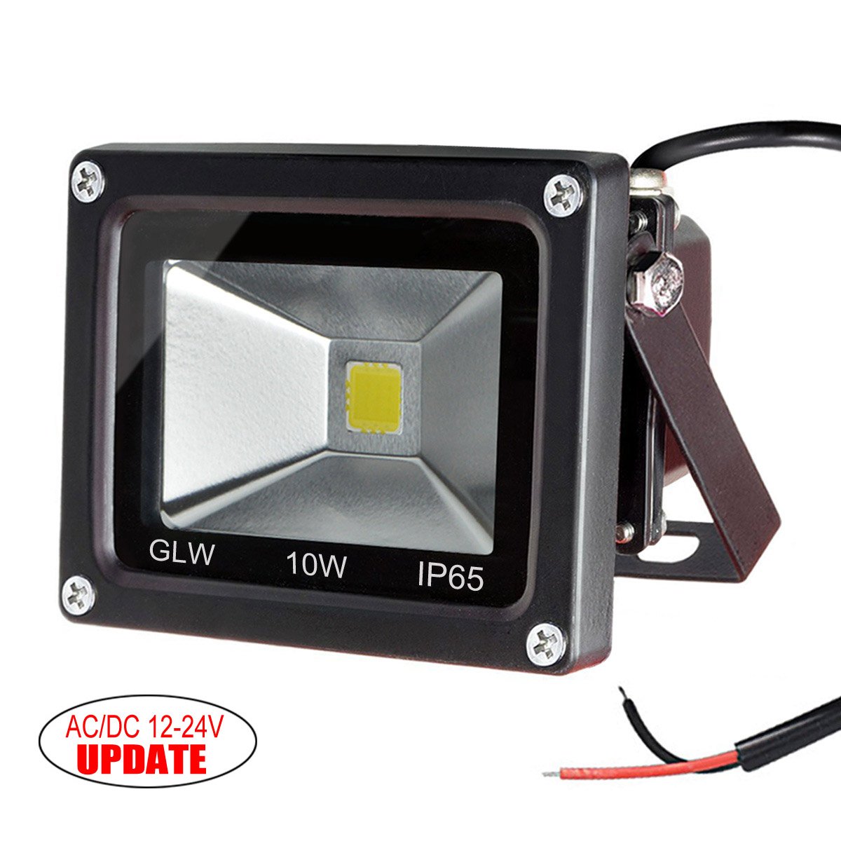
I should call these “ubiquitous 10 watt low voltage LED lights”. I have a bunch of these at my cabin, and they are pretty well made; nice heavy aluminum housings to get rid of the heat, decent mounting options. This go about 18’ up in the eaves to project a nice smooth light down on the yard. I bought 4 of them.

Image result for leonlite pathway garden light

These are the pathway lights. I spent a lot of time trolling the chinese marketplace sites (aliexpress/alibaba etc.) looking for some decent lights that were cheap. What I found is that you can either buy high end lights that are $45 each, or you can buy part of an endless supply of really cheap and crappy solar lights, but nothing in between. So I settled for these from Amazon. The Amazon product is not linked because it has changed underneath to some other lights; suffice it to say that I bought 12 of these for about $13 each. These will be spaced out in the beds to make them look all pretty-like.

Astute readers will note that I’m using 36 watts for the pathway lights and 40 watts for the floods (or only 30 if I only put up three). That leaves me about 25 watts to spare. Some may go to accent lights on the north fence, and others might go for some lighting to help get to the hot tub. If I was smart, I would have gone bigger than 100 watts, but that can be replaced if necessary later on.

This is a nice little power MOSFET that will be switching the landscape light circuits. Why this MOSFET? Well, let’s look at the datasheet.

First off, MOSFETS are far nicer to use to switch loads than bipolar transistors. Bipolar transistors have significant downsides; you need quite a bit of current to switch big loads (the overhead lights will be about 3 amps) or you need darlington transistors, and because of the fixed collector/emitter voltage drop, you lose a lot of energy in the transistors, and they get hot.

This little MOSFET will happily switch 44 amps @ 10 volts and 100 degrees C, which is *way* more than it will ever see. It will switch 3 amps with 3 volts on the gate and 11 amps at 3.5 volts; the ESP runs at 3.3 volts so it will be enough to switch the current I need (if I needed big current, I’d need a bipolar driver in front to push the voltage higher). And – like most power MOSFETS – it has very low resistance between the drain and source (8.7 milliOhms with 10 volts on the gate). What that means is that it dissipates almost no energy as heat when on, and I can run it without a heat sink; it will at most get very slightly warm. And it also means I’ll send a full 12 volts out to the lights.

I guess I could also show the big 200’ roll of landscape cable. In the old world of incandescent lights, I would have needed to power these lights with a loop or maybe multiple wiring runs; in this world, the floods have their own power supplies so the voltage to them isn’t critical and the path lights don’t pull enough power to result in much voltage drop.

For the box connections, I’m thinking I will probably go with some molex connectors; that gives me a fairly safe way to hook up the AC to the power source and that way I can disconnect the whole module.


Back yard landscaping

A few years, we paid some landscapers to do some work on our back yard; they did a nice paver patio and walkways, evened out the slope, and re-sodded the now elevated lawn.

There were, however, a few issues.

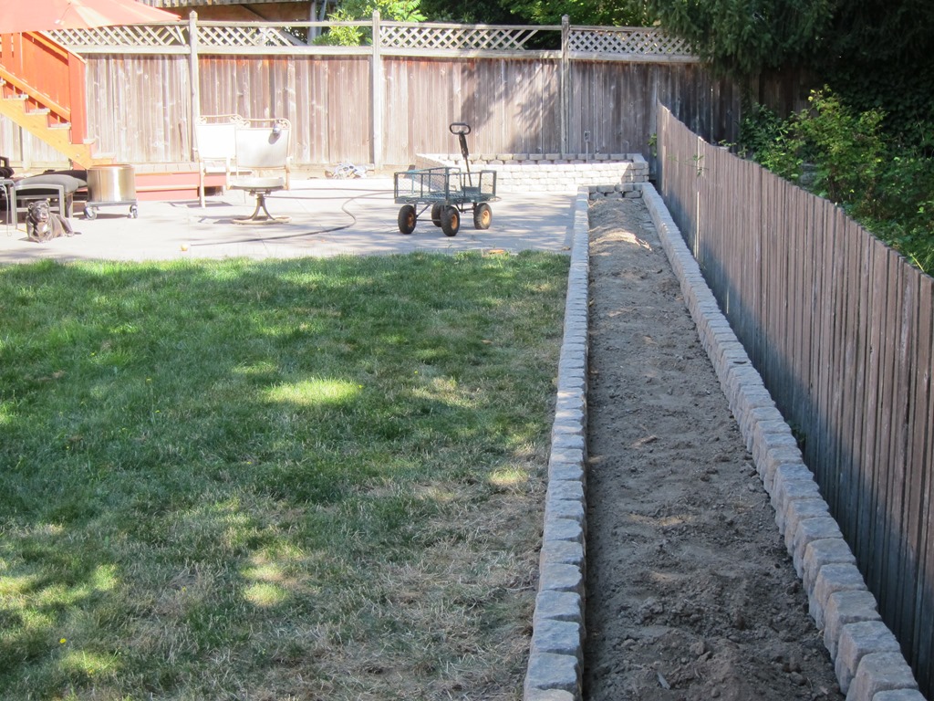
They used big landscaping blocks for the back of the beds, so there wasn’t much space for the plants in the beds, nor was there enough height to have a reasonable amount of soil, nor was there a barrier to contain the mulch. So, they didn’t work as well as beds.

And all we had was beds, so the yard wasn’t very interesting.

Oh, and we had one more issue; the decent back fence we put up was now about 12” below the current grade, which is just weird.

This summer, we are finally getting around to fixing those issues; this is partly to realize the design we had our landscape architect do, and partly to add in the things that we wanted. I’m too lazy to find the real before pics, so you’ll need to settle for “early in the process pictures”.

IMG_9268

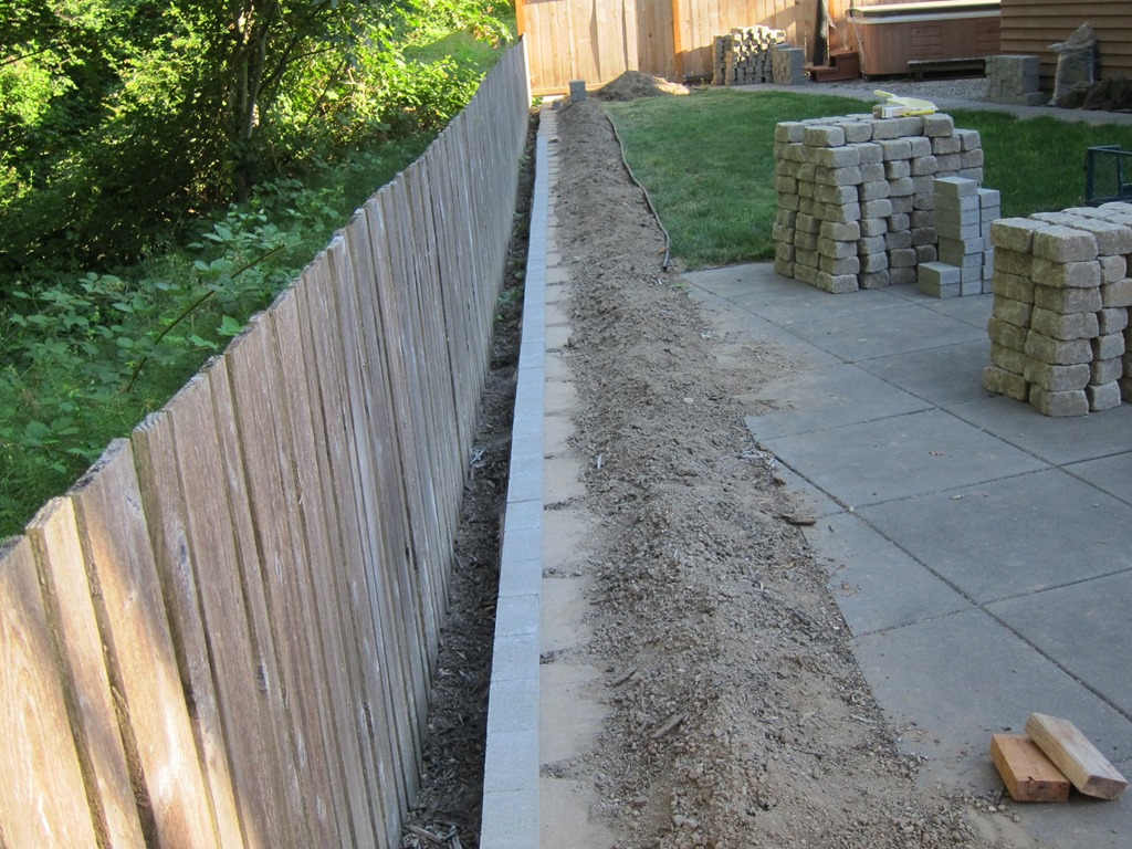
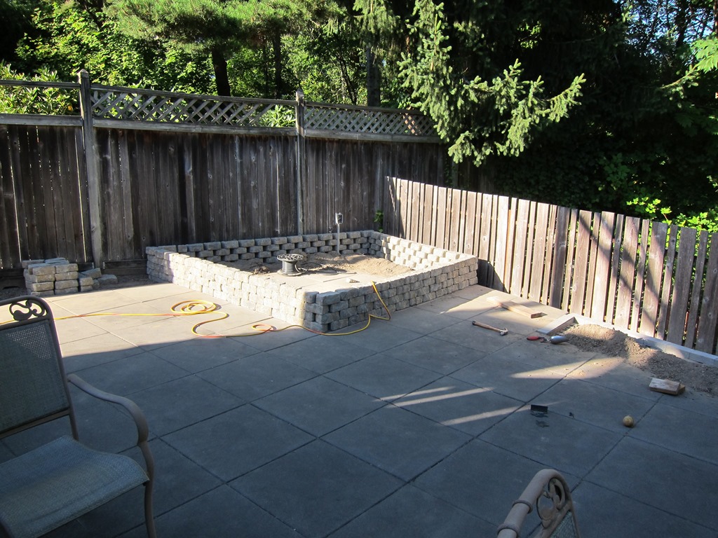
This one shows the lovely back planting bed and the weird fence. Careful observers may be able to see some of the blocks we are using in this picture. The concrete bricks on the back are to deal with a level problem; the pavers are about 2” higher than the row of blocks that make up the back edge, so the 2 1/4” thick grey pavers make up the difference. They will not show in the completed project, so we went with the cheapest ones we could find.

I don’t have any pictures of moving blocks; suffice it to say I moved 700 blocks @ 8 pounds each, or 5600 lbs of blocks from the driveway down the hill into the back. And 240 of the bricks.

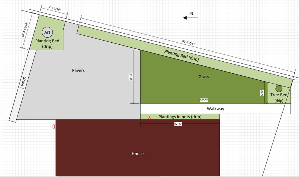
Here’s a rough drawing of what we’re aiming for:

image

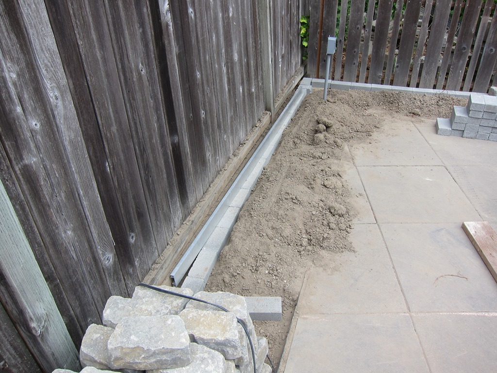
On the left side the big bed will partly cover the corner of the patio and partly be in the dirt. that required me to get a nice line of concrete bricks for the blocks to set on. It looks like this:

IMG_9265

I’ll talk more about how I achieved that soon.

And then it’s merely a matter of laying the blocks out where you want them, and a small bit of block cutting with a 7” angle grinder and a masonry wheel. It looks like this:

IMG_9266

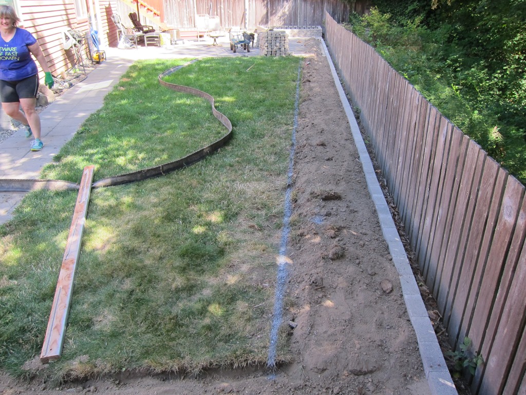
Over to the big bed. We need to cut the grass back a bit for the bricks to fit. The front of the bed is measured from the bricks next to the fence, an old 2×4 is used as an edge, and a line was painted in the grass.

IMG_9269

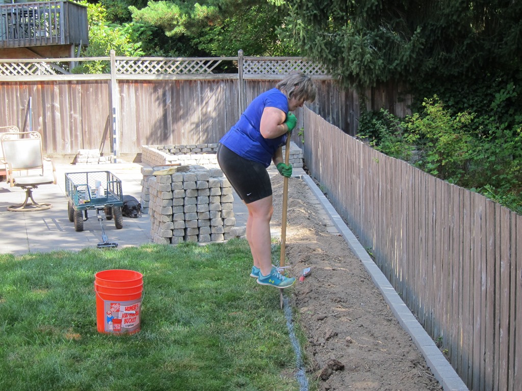
The project lead spent a few minutes cutting the grass away.

IMG_9270

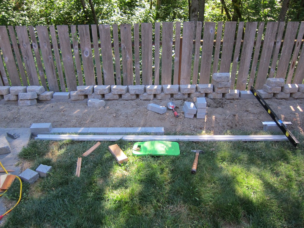
Then it’s time to set the bricks. The appearance of the final wall will depend highly on how well the bricks are set; the top of each brick needs to be in the right location (x & y), the right height (z), and also be in the right plane left to right and front to back. Here’s how I did it:

IMG_9274

The block on the far left is set to be planar with the patio and the right distance from the extra block on the back. That is one reference.

The second reference is on the right. That stack of two blocks is adjusted so the front face is the right distance from the back block, level to the back block at both the left and right ends. And then the top of the block needs to be planar with the bottom of the level and the long straight edge sitting on the left block. That takes a few iterations to get right, so 10-15 minutes to get a guide block in.

And – because they need to stay in those positions – each block has to be beaten in place with a hammer and a block of wood to compress the soil underneath.

Once the reference is, then it’s merely a matter of placing each block and using the straight edge to make sure it is where it needs to be. Along the whole length most of the bricks are less than 1/16th off on any dimension. Yes, that’s probably overkill, but getting them to 1/16th isn’t much harder than getting them to 1/8th, and it makes the landscape blocks sit much better.

There’s about 40’ of blocks to set along that bed plus another set around the right planter. So, it took quite a bit of time – probably 6 hours just on that part. But, eventually, you get them all done, you can put the landscape block on top, and you end up with a bed that looks like this:

IMG_9281

Which is honestly pretty damn straight.

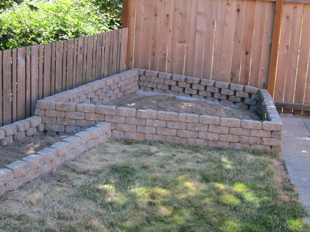
Which takes us to the right corner bed:

IMG_9280

I’d like you to pay attention to how nicely the back bed and the corner bed blocks are woven together. And I’d like you to ignore the wall next to the fence.

We basically had a problem; the blocks the landscapers put in on the fence side are higher than those along the back, so we needed to adjust. I ended up doing the whole bottom row in mortar so I could deal with the 2” difference across the thickness. It came out okay.

The day after I dog that done, I realized that the right thing to do was to put the blocks on that wall flat without bricks, and then taper from a brick down to nothing along the *back* wall next to the fence. That is the proper thing to do and I have another bag of mortar, but the project lead assures me that nobody will notice once we get the bed planted. If we need to redo it later, it will be simpler.

That’s the current state.

The future will bring soil, drip irrigation (partly in; you can see a connector in the last picture if you look closely), landscape lighting, mulch, and plants.

The fence will be elevated to be a bit higher and moved closer to the blocks. The mysterious art will be installed.

And if you think that this project wouldn’t include some custom electronics, then you don’t know me very well…


Connecting the Eagle Controller to a WS2812 strip

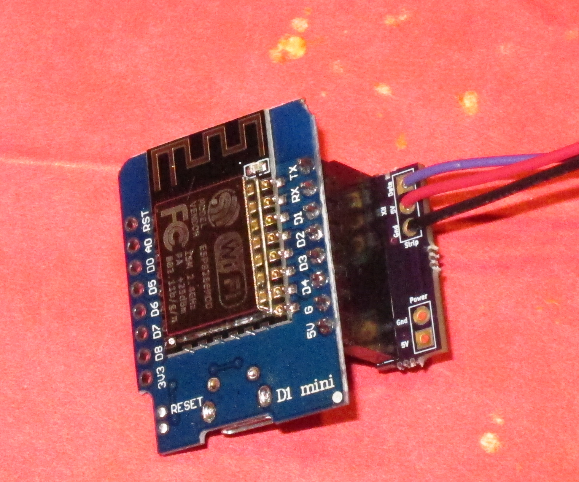
To connect the Eagle controller is simple; there are only three connections to make:

image

The following connections need to be made:

  1. The black wire from the strip (or globe) should be connected to the ground pin
  2. The red wire should be connected to the 5V (5 volt) pin
  3. The data wire (purple from the globe) should be connected to the RX pin.

This will be enough for the controller to work if powered through the USB mini jack. This is fine for testing, but has several drawbacks:

  1. Each WS2812 LED will draw 60 mA of current if it is full bright. There are 33 on the globe, which means that full white will draw 60 * 33 = 1980 mA = 2 amps. The USB connector will not be able to supply that amount of power, so you will not get full brightness.
  2. The Eagle controller has a diode so that external power will not power the USB jack. This means that instead of getting 5V to the strip, you get about 4.4 volts to the strip. It also means that there is a lot of power being dissipated by that diode, and it will get *hot*; hot enough that it or other components on the board may fail.

To avoid these issues and enable full brightness, you need an external 5V power supply that can supply sufficient current. It can be connected to the 5 volt and ground connections.

Using the connection board

Newer versions of the controller ship with a small adapter board to make these connections easier.

image

We will start by soldering a male header to the series of pins on the right side of the controller with the pins sticking out underneath. You can get by with just using pins for 5V, ground, and RX, but there’s no harm in soldering all 8 pins. Here’s how I do it:

image

Place the header pins into a solderless breadboard with the appropriate spacing. We put pins in on both sides so the board will sit level, but we are only going to be soldering the ones at the top.

This step may have been done for testing purposes.

It should look like this when the pins are soldered:

image

Now, we need to solder a female header to the adapter board:

image

The header should stick out above the board in this orientation. To do the soldering, I balance the board on the female header and use the other strip of female header to hold the board level:

image

Solder all 8 pins across the top.

image

This is the controller with the male header and the adapter board with the female header. The male header simply plugs into the female header.

image

The wires to the LEDs are then connected to the upper 3 terminals on the adapter board, and the 5V power supply is connected to the lower two terminals.

Compact option

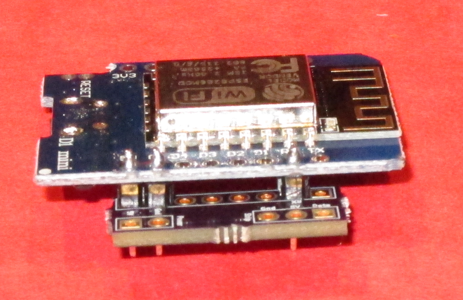
If the controller and the adapter are too thick, there is an option that is thinner:

image

In this option, the female header is omitted and the adapter board is soldered directly to the male header pins.

If you are really tight for space, you can solder the male header, remove the black plastic that separates the pins, and then slide the adapter board right next to the controller.


Still Mad about You…

I recently came across a podcast where Paul Riser talked about “Mad About You”, and the obvious question popped into my head.

Would Mad About You hold up?

My beautiful bride and I enjoyed watching it considerably when we it was first on and we were in the first decade (roughly) of our marriage. But I’ve learned to approach things that I’ve liked in the past with care. Sometimes they hold up pretty well, but other times – for various reasons – they don’t hold up at all. Sometimes the memory is much better than the reality.

So, I dusted off the my search engine and found a few episodes to watch. Which gave me enough evidence to approach the wife, and we ended up watching all 7 seasons (on Starz through Amazon, which is the only place we could find it except for some really crappy quality episodes on Youtube).

And the result?

It holds up surprisingly well. Well enough that we were both sad when we finished the last season. Mad About You uniquely captures what it’s like to be in a couple; the way that the two of you are the sum of your strengths, the amount of work it takes to keep that kind of relationship going, and how things can get difficult despite both people trying their best.

And how your partner can simultaneous be somebody you can’t imagine living without and the most annoying person that you know.

There are some issues with the show; the other characters necessarily need to bring conflict in and sometimes are annoying and not all of the story lines are great – especially the cameos that feature notable actors. But they are mostly very good, and to this married-for-a-long-time guy, much of it rings true. And the humor is good.

*Highly* recommended.


Easy PCB stencil creation and alignment

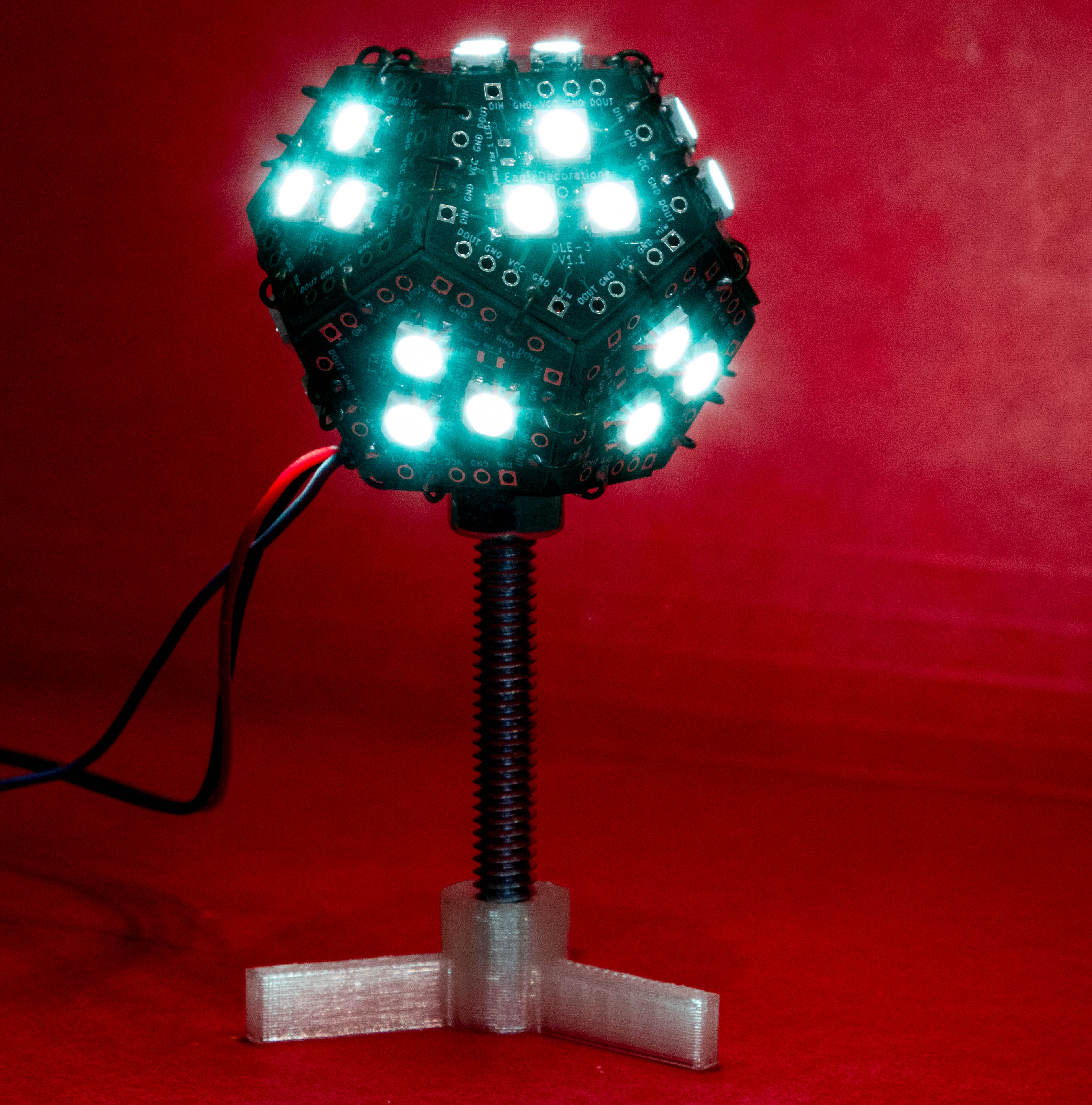
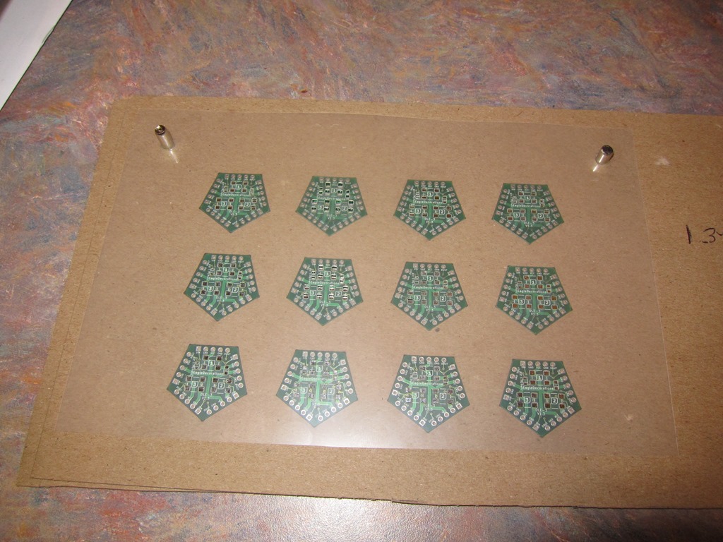
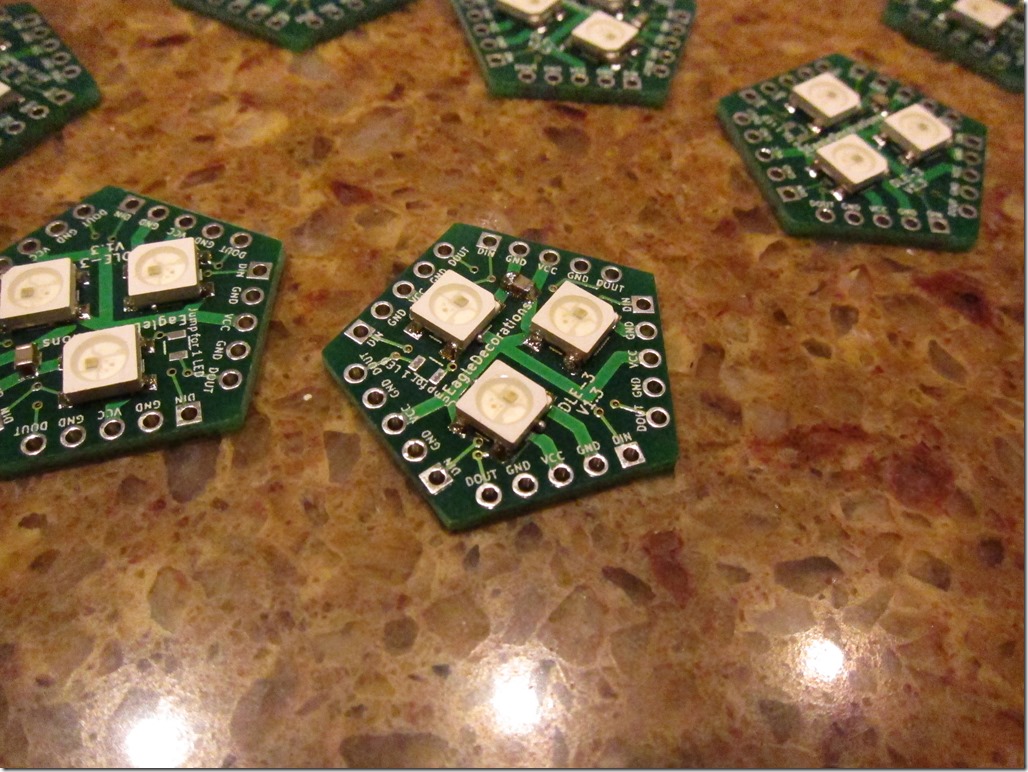
I have a product that I’ve just started selling; it’s a LED globe/Soldering challenge kit that looks like this:

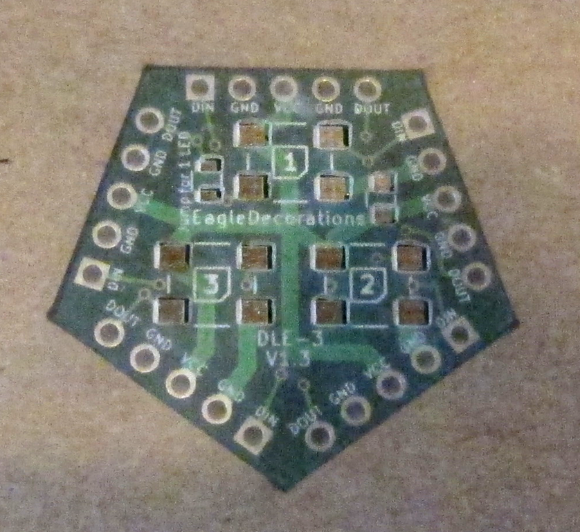
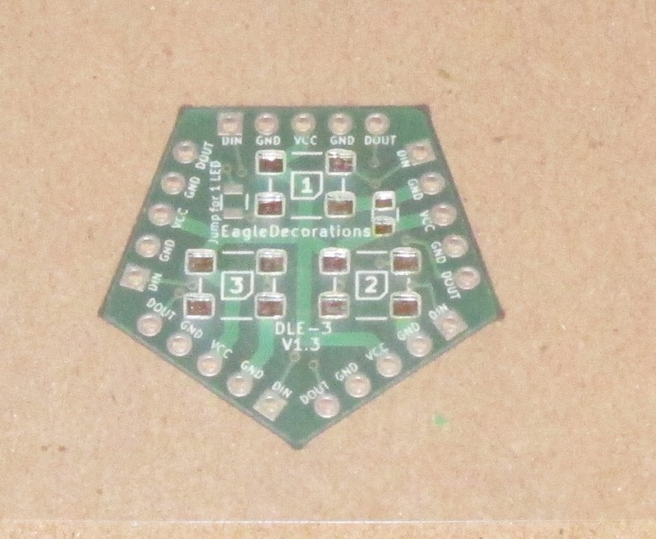
It has a PCB that looks like this:

image

For my first run, I needed to make 10 kits, and each of them has 12 of these boards, so that’s 120 boards.

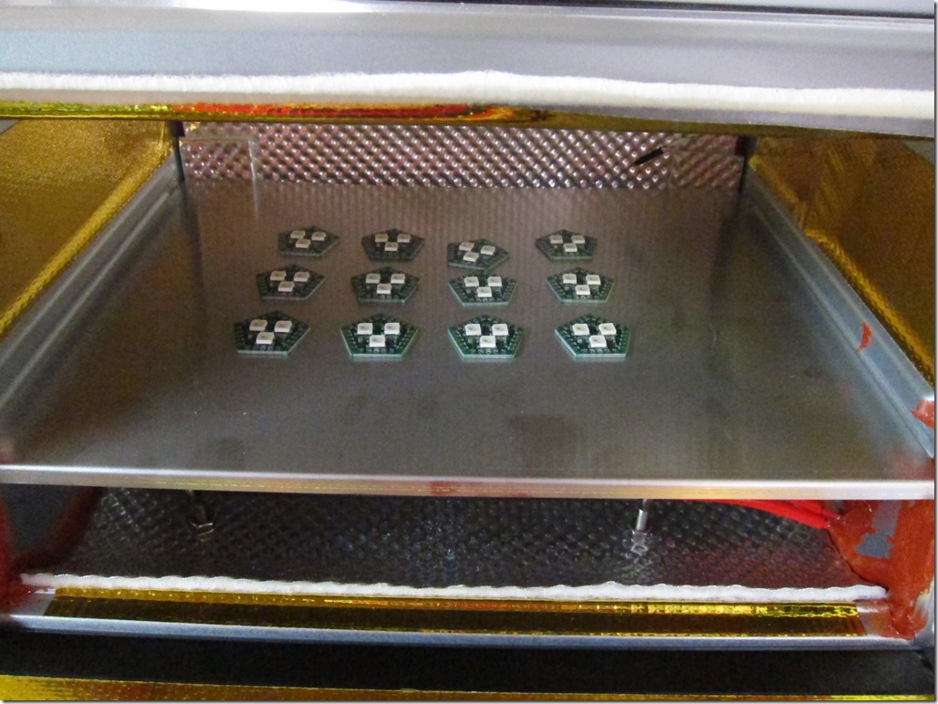
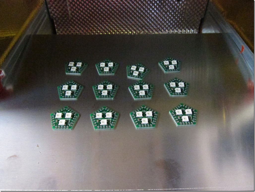
I’ve been hand-soldering the prototypes, but it takes quite a while and my eyes aren’t as good as they used to be. I just built a reflow oven based on the controleo3 kit so that I can reflow in cases like this.

Which means I need a stencil. I could easily just order one up, but that means I’m going to have to align this tiny stencil with the board 120 times. Doesn’t sound like fun…

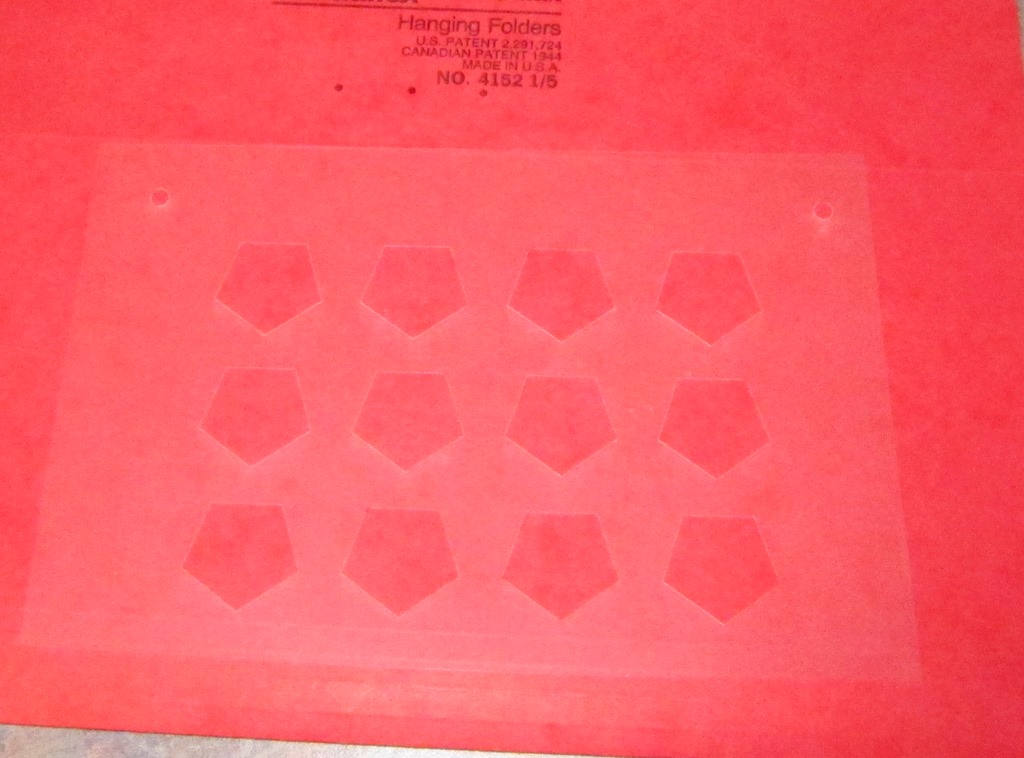
What we need is a way to apply solder paste to a set of boards in one shop and make it repeatable. In the woodworking world, that would call for building a “jig”, or perhaps a “fixture”. Which is what this post is all about; we’re going to use a laser cutter to make all of this oh so much easier.

Teaser photo

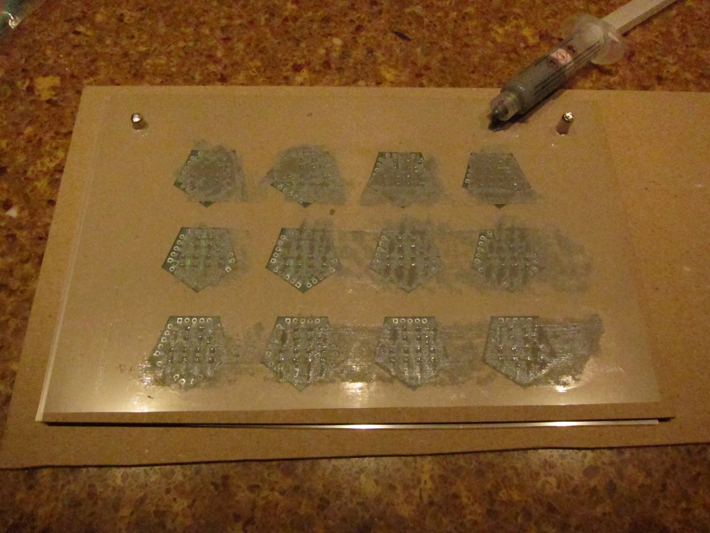
Here’s a teaser photo of what we’re going to build:

IMG_9248


Get your board outline and paste mask in SVG format

Since I’m doing my design in Kicad, this was really easy; just go into your design, click the plot button (like you would to create Gerbers), choose the F.Paste and Edge.Cuts layers, and set the plot format to SVG. That’s it.

Well, actually, you should probably modify your paste cutouts to be a bit smaller than they are by default; see this excellent reference for how to do it in Kicad.

If you are using a different package for your design, search online for how to make stencils from it; it will tell you how to export.

Create a combined image in Inkscape

The export give us two separate files; one has solder pads, and the other has the board outline. The first step is to combine them together.

Open both images in Inkscape. Change the color of the edges to blue and the color of the pads to red. We do this so we can control which ones get cut and which ones don’t in the laser cutter.

You do have access to a laser cutter, right? Because if you don’t you’re wasting your time.

Anyway, that gives us two instances of Inkskape:

imageimage

We now need to combine those two together in another image.

Create a new document in Inkscape with File->New. Go to the pads Inkscape version, do a Select All, then a copy. Switch to the new document, choose edit->paste in place.

Repeat the operation with the edge cut Inkscape version.

If your are of true character and have a pure heart, you will get the following:

image

Edit->Select All, then Object->Group. That puts this all together into a single object.

Save the document away with a catchy name like “Combined”. We now have the image for a single board.

Duplication

We now need to create an array of objects; in my case, it’s going to be an array of 4 wide and 3 high. We’ll start with the four:

  • Select the single object.
  • Paste it three time. Line them up approximately. It doesn’t matter like this.
  • Bring up the align and distribute menu. You will never find the icon to do this, so try CTRL-SHIFT-A. Hover around until you find a icon that says “align top edges”, and pick it.
  • Distribute the empty space using “make horizontal gaps between objects equal”.
  • Mine looked like this:

    image

    Those are way too close together for me. Undo the distribute, move one of the edge ones out, and redo the distribution.

    image

    That’s better. The actual spacing is up to you. Group them together and save.

    We’ll do the same thing for the rows; create two copies, align the left edges, and then distribute:

    image


    Save. Looks like we’re done, right? Not quite, there’s one more thing to add:

    Indexing

    This will work fine, but we would have to hand-align the stencil with the boards, and that’s going to be a bit of a pain to do. What I want is a way to make it repeatable.

    The secret is pins. Pins, I say!

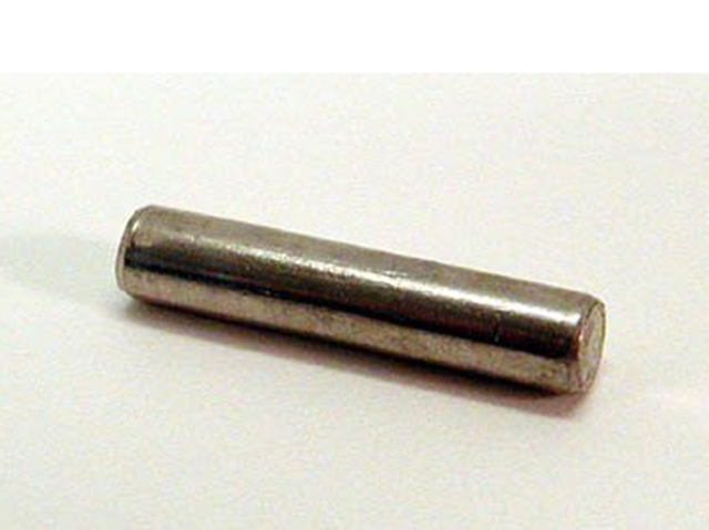
    A trip to my local hardware store yielded two 5mm shelf support pins. They are likely longer than I need and I might cut them in half for my usage. They look like this:

    image

    We are going to use them for alignment, which means we’ll need some 5mm holes.

    Flip back to inkscape, and draw a circle. Pick the selection tool, and up under me menu bar, you’ll see the width and the height. Set both to 5mm:

    image

    Set the fill color to full green, set the stroke color to black, flip over to the stroke style, and set the width to 0.1mm. It should look like this:

    image

    Put this one to the upper left of your objects, copy it, and put the second object to the upper right. It should look something like this:

    image

    Note that it doesn’t look that great. That’s okay, we will fix that now.

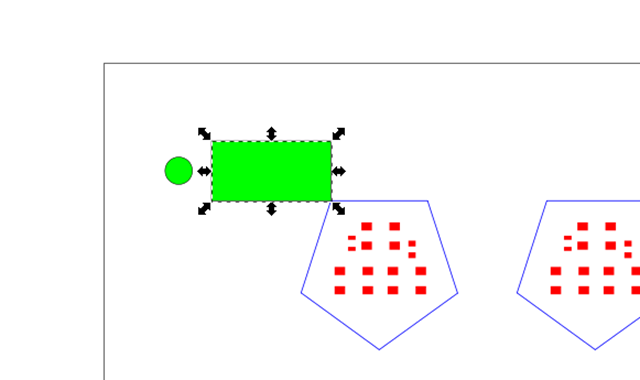
    Draw a rectangle from one corner of your objects to a point spaced away; this will be the pin location. Something like this:

    image

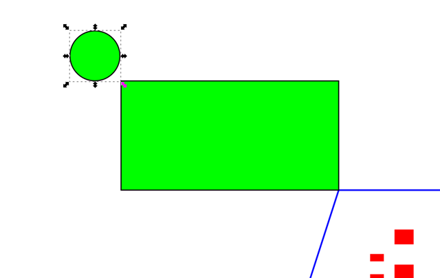
    Then drag the circle so that it is at the corner:

    image

    I call this “using a gauge block”. Move the rectangle to the other corner and use it to align the other pin as well, and then delete the rectangle. They don’t have to be symmetrical for the technique to work, but I like things to be regular.

    I ended up with this:

    image

    Why so many items and so many colors? We will use them in the cutting process.

    The jig that we created will be a sandwich of different materials; from bottom to top they are:

  • On the bottom will be a piece with only the peg holes cut into it; we will use the black circle outline for those cuts.
  • Next up we will have a piece with the peg holes and the edge cuts, so we will cut both black and blue.
  • Finally, for the top, we will cut the actual stencil; it will have the circles cut for alignment and the solder pads.
  • There’s a bit more complexity than that; I’ll talk about it when I get to the actual cutting.

    Materials…

    The goal of making the fixture is to make laying down the solder paste easy, so the materials need to be chosen carefully.

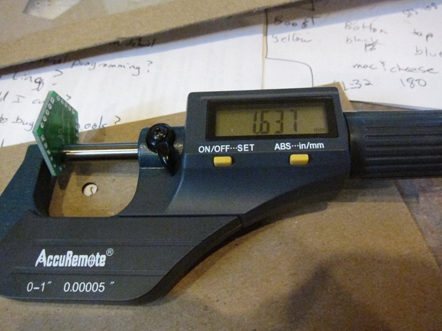
    My PCB house says that they material they use is 1.6mm thick. I don’t trust material thicknesses, so let’s check:

    IMG_9234

    That’s pretty close, just a 0.04 mm thicker than I expected.

    For the main parts of the fixture, I needed something that was fairly rigid, fairly cheap, and the right thickness. I thought about hardboard but decided to go with what is called “chipboard”; I’m not sure why it is called chipboard because it’s just very compressed cardboard, the kind you find at the back of tablets of paper.

    After looking it locally in vain, I ended up heading to Amazon, where I came across this:

    Grafix Medium Weight Chipboard Sheets, 12-Inch by 12-Inch, Natural, 25-Pack

    Grafix Medium Weight Chipboard Sheets, 12-Inch by 12-Inch, Natural, 25-Pack

    25 sheets was more than I needed by about 24 sheets, but it laser cuts well and is decent for prototypes.

    The thickness isn’t listed in the specification, but that was one of the questions asked, so I looked at the answers and found that is was:

  • 1/16th of an inch at most
  • .057” (1.45mm) (from the manufacturer)
  • Almost exactly 1.5mm per board, determined by measuring a stack
  • 2 mm
  • It’s nice to have some many helpful answers. I could probably make most of those work, so I ordered it. It showed up, and what did I find?

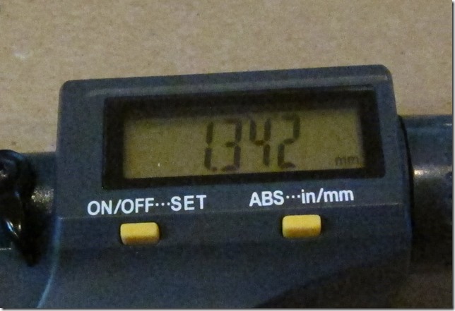
    IMG_9233

    So, the correct answer was “none of the above”. It is notably a full 0.1mm thinner than what the manufacturer says. I’m not sure that just means there is more variance than the manufacturer says or they are just going thinner. Luckily, I can work with that thickness

    For the actual stencil, there were a few choices. You can cut them out of Kapton or out of Mylar. I went looking for Kapton in the common stencil thicknesses of 3 or 5 mil and didn’t find anything that looked good and cheap. So, looking at Mylar led me to Amazon, where I found 4 mil mylar, also in a package of 25.

    What is the mylar thickness?

    IMG_9237

    A quick bit of conversion shows me that the sheet is just over 3.8 mils thick, which is fine.

    Materials in hand, I headed out to my workroom where the glowforge lives to do some cutting.

    Some cutting remarks

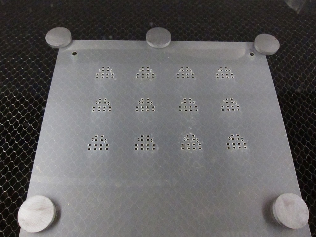
    First up was cutting the mylar. The Glowforge has a significant bit of airflow to pull fumes out, and 4 mil mylar would blow right off the crumb tray, so I used ceramic magnets to hold it in place.

    One of the problems with mylar is that when you heat it up it tends to shrink. Since the holes I want to cut are rectangles, the laser head needs to stop at each corner, and at least on the Glowforge, it doesn’t do anything to the beam, so you will get a lot of power right at the corner. Maybe we could break the rectangles into two cuts and carefully manipulate the laser power, but I’m not that confident it would work. If you want to cut it normally, I would recommend trying low speed and very low power.

    Luckily, there’s another option. We can do a raster engrave of the squares and just ablate away all of the material in the middle. This avoids the “stuck in the corner” issue, and since the power level is fairly low and the start and stop is done by turning the laser on and off, there should be fewer issues.

    The right way to do this is to put a piece of paper under the mylar and figuring out what power and speed settings cut through the mylar cleanly but barely touches the paper. I grabbed some settings from the Glowforge Forums and used those.

    For the mylar, we are engraving the red paste mask part of the design and the green circles. The blue board outlines are disabled

    IMG_9228

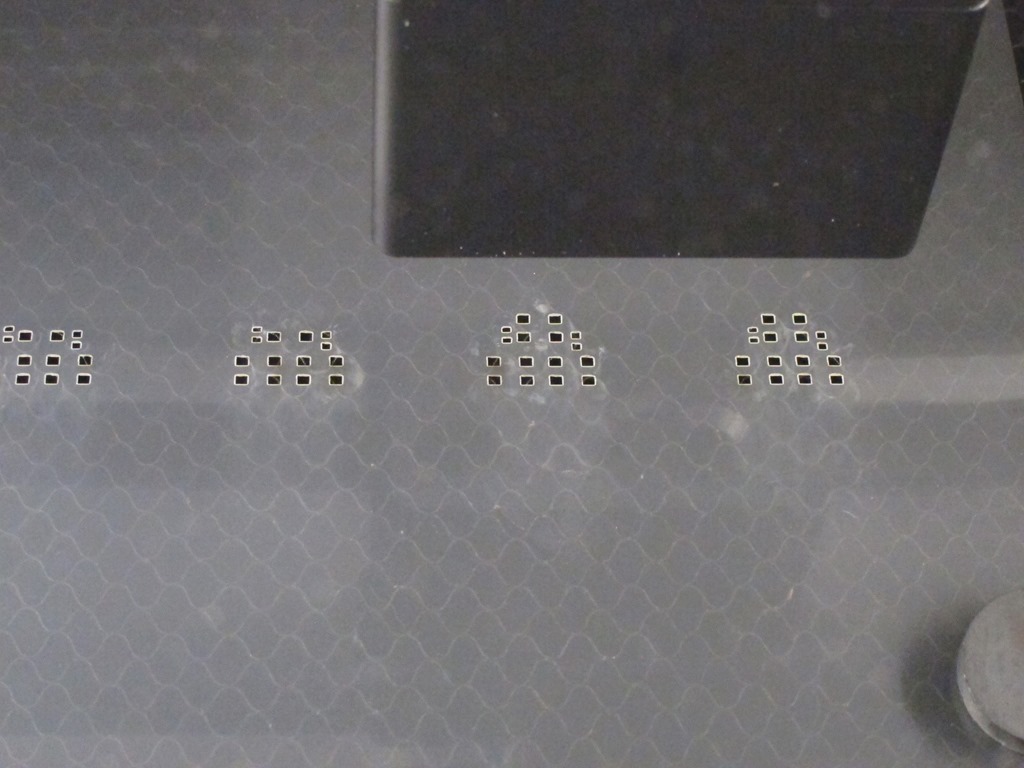
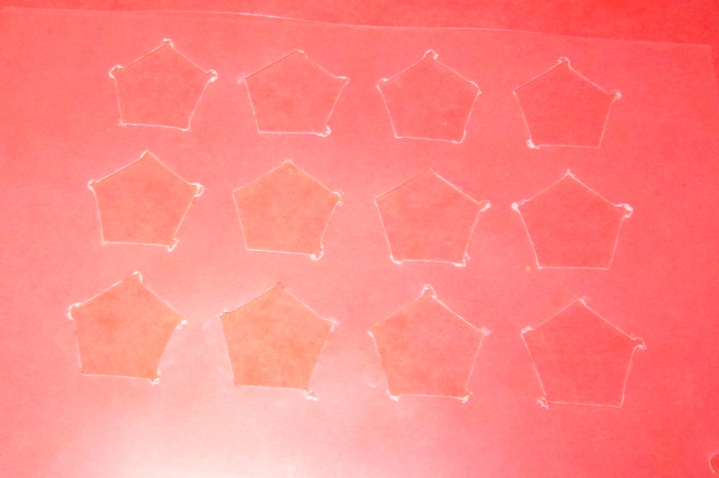
    This is the first row being engraved. You can see that there is a little sloppiness in the outlines, but in general they are pretty much all the right size. Here’s the final sheet:

    IMG_9229

    The stencils look like what I expected and the 5mm holes look appropriate as well. Maybe this will work after all…

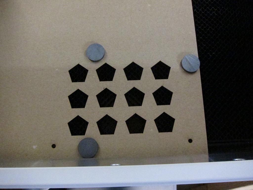
    Next up was cutting the top piece of chipboard with the board outlines. The board outlines are turned on in cut mode, the circles are switched to cut mode, and the paste mask is turned off.

    IMG_9231

    I previously did a proof of concept on this step, so I knew it was going to work. Nice clean cuts.

    And finally, the base cardboard piece. All it has is the circles, so it looks like the above picture with just the circles.

    Assembly

    Sandwich time!

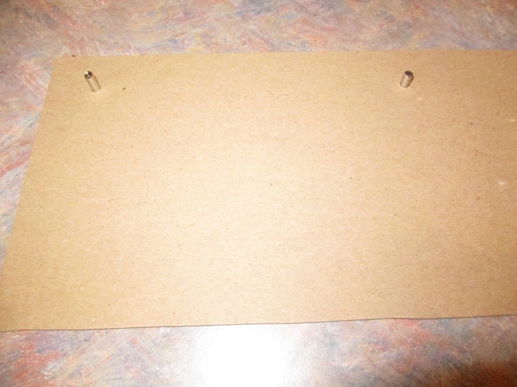
    We start with the base.

    IMG_9239

    And then add in the 5mm pins. This posed a bit of a problem; the pins have a nice chamfer on the end so they didn’t stick into the cardboard very well. I solved this by cutting one of the pins in half with a dremel and an abrasive wheel. I should also note that at 4.96mm, they are just slightly undersized.

    IMG_9240

    So, it turns out that the 5mm holes aren’t quite 5mm in size; they are just a bit smaller so I need to force them in a bit. A friction fit is good, but a forced fit is less good. This is exactly the sort of stuff you learn if you do test cuts. Well, perhaps version #2…

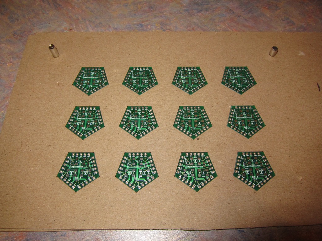
    Adding in the board layer, which aligns quite well with the bottom layer. And the boards fit with just a little bit of movement, which is just about perfect. They are proud (above the surface) by about 0.3mm, which I determined by math. That will probably be okay, but if I want/need it to be closer, I can easily shim it out with some mylar, which at 4 mil is almost exactly 0.1mm thick.

    IMG_9241

    The moment of truth. Adding on the mylar layer. The mylar holes are also too small, perhaps more too small than the cardboard.

    IMG_9242

    What sort of result did we get? It mostly looks pretty good. There is a tiny bit of bowing in the mylar, which I think is due to the “too small holes” part, but it’s probably good enough right now. The alignment is offset a bit but it’s certainly usable:

    image

    Revision #2

    The nice part about building a jig this way is that the materials are cheap and doing another set of cuts doesn’t take much time, so it’s easy to do another revision.

    My first goal was to fix the circles so that they better matched the pins. Since I set them to 5mm explicitly, I figured I’d need to make them a little bit bigger. So, I opened up the design in Inkscape, selected the circles, and what did I find?

    4.95mm

    Huh? I honestly set them to 5mm, but now they are smaller.

    A bit of experimentation revealed what was going on. I am used to working in Visio where the dimensions are inherent properties of the object, so a circle that is 5mm in size is always 5mm in size.

    Inkscape is different. When you way that a circle is 5mm in size, you are setting the outside diameter, and that includes the line width. So, if you set the size of the circle and then change the line width to be thinner, your circle will no longer be 5mm in size. More like 4.95mm.

    Discovering this made me happy, as it meant that the bad fit was from something I understood, not something I did not understand.

    That was a really quick fix, and I cut the new pieces and put the sandwich together. This worked much better; everything went together much easier, and the alignment was better:

    IMG_9245

    Looking closely at the entire stencil, the errors look pretty random. It’s by no means as nice as the commercial stencils I’ve had cut, but it seems serviceable enough.

    I did want to deal with the spacing issue so I could get the board thickness a little closer to the fixture thickness. It turns out that 4 mil is almost exactly 0.1mm, so I cut a spacer as part of the previous revision. Here’s a crappy picture of my first attempt (the stencils are really hard to take pictures of):

    IMG_9246

    That is what happens when you try to cut mylar with high power; the beams stays on at the corners and totally blows it out. I *thought* this would still be usable, but all that melted mylar globs up and is way thicker than 4 mil.

    I cut a second version as part of the revision, using the lowest power that would work.

    IMG_9247

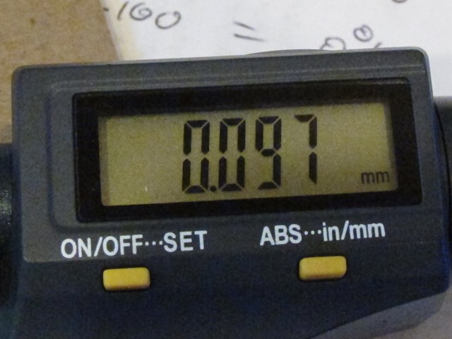
    That is definitely much better, but when I grabbed my micrometer and measured it, it turns out that the mylar melts a bit where it’s cut and the edges are about 0.2mm thick. Since I was hoping for something like 0.3mm total, just using this spacer should be sufficient.

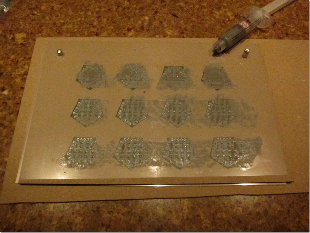
    First pass with solder paste:

    IMG_9248

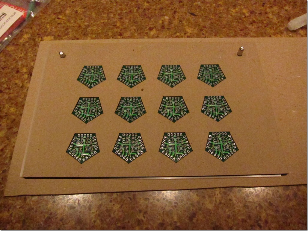
    And the resulting boards. It was mostly good enough; needed a bit of touch-up for a couple.

    IMG_9249

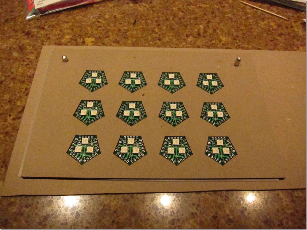
    LEDs and decoupling capacitor added:

    IMG_9250

    Into the oven:

    IMG_9253

    And all done:

    IMG_9254

    The reflow worked well; 11/12 were fine at the start, and I replace one LED to fix the others.

    IMG_9256

    Round 2

    Round 2 was more of a production run. I changed my technique so that after putting the paste on, I would peel the stencil up and then separate the layers to let the boards fall out the bottom. This worked pretty well. I did 9 rounds plus 4, or 112 boards total, which used up most of my LEDs. Two rounds in the oven, and I had 111 functional boards.

    I really need to build a new test rig; the current one only tests 3 at a time and it’s a pain to load them.

    Summary

    I’m quite pleased with the way that the jib turned out; I pretty much works exactly the way I had hoped, and I can apply paste and populate a set of boards in about 10 minutes.


    Training Wheels Very Very Late Spring Canadian Century

    Because of a conflict, I was unable to ride Flying Wheels this year, but since I have some bigger rides later in the summer – including DORMAR (RAMROD backwards) – I wanted to get in a nice long ride.

    So, I decided to go out and ride a century. But just riding the Flying Wheels route would have been too easy, for a couple of reasons:

    First, I live a little over 5 miles from the starting point, and if I ride there and back that would be an extra 11 miles or so.

    The second reason requires a bit of an explanation… I’ve been leading rides around the Eastside for a number of years now and did my own routes before that. So… I have a particular attitude about routes. Perhaps a Venn diagram would help:

    image

    Rare is the route that I won’t find something to complain about. Some of my complaints are based in fact, but many are based on reasons.

    So, anyway, a little route-tweaking was in order. The big changes I made were:

    1. Starting the route at my house
    2. Ending the route around the south end of Lake Sam to make it a little simpler; otherwise I would ride all the way to the North end just to ride South again.
    3. Getting rid of about 7 miles of farting around in North Bend. I know that they need to find some extra distance someplace and this was an easy way to do it, but I really find that section to be tedious.

    That gave me 99.8 miles, or something like that.

    The ride

    I woke up, skipped breakfast – as I generally do before long rides these days – and got dressed. The weather was in the mid 50s, trending into the low 60s later on. I positively hate that temperature range; it’s just a bit too cold for bare legs for me, but it’s going to be too hot for leg warmers later on. Arm warmers are easy to fit into a jersey pocket; leg warmers are a lot harder. Unsure, I went and stood outside for a few minutes, and decided that if the sun held up, bare legs would be okay.

    Did I mention that the forecast was for partly cloudy? Yeah…

    Before I got dressed I drank down 3 scoops of SuperStarch with a half scoop of Endurox to make it slightly less repulsive. The SuperStarch is based on cornstarch, and a big glass of water with a lot of suspended cornstarch tastes exactly as good as you think it does.

    In my pockets was a ziploc bag of Cheez-its that had seen better days and a single Honey Stinger Chocolate Waffle. I’m experimenting with a bit of carb supplementation recently. I had my arm warmers on and was wearing a stuffable vest.

    I rolled out of the driveway at 8:15 and immediately ran into a problem. Well, two problems. The first was there was a bit of a headwind coming from the North, which would slow me down and make things a bit cooler. The second was that my legs hurt and felt flat.

    After an 8 mile warmup, I came to the base of Inglewood hill, the first on the docket for the day. If you climb Inglewood during Flying Wheels (I have been known to ride up the harder Sahalie drive climb instead), you will know that it is somewhere between a hot mess and complete carnage. I avoid it on my rides because I just don’t like it very much, so this was a rare solo ascent for me.

    On climbs, it’s great if you can find a rabbit. A rabbit is a rider in front of you that you can try to catch. Ideally, the rabbit is just a bit slower than you so that you can make up some time on them during the climb. Early on a weekday morning, there were no rabbits to be found, but halfway up I looked to the side and found that I had a deer who was pacing me just off the side of the road. She’d stop for a moment, I’d get closer, she’d run forward a bit and stop, and the cycle would repeat itself a few times. We eventually came to a road, where she hesitated and I tried to figure out how I could bail because 25’ is way to close, and then she took off into some woods. The rest of the hill was soon dispatched. Not one of my better climbs, but I was at the top.

    The next hill is 236th, climbing from 202 up into the Redmond Ridge/Trilogy developments at the top of Novelty hill. It will surprise you not at all to find out that I think this routing is a mistake. I don’t think it’s necessarily too hard for the century riders, but I do think that it’s too hard for the 47 and 67 mile riders. In the old days, we went east and climbed up Ames Lake; though that does require a left turn that isn’t the safest, I still think it’s a better choice. The century riders could climb up Union Hill Road to get to the same spot as they do currently, or you could just split early and send them up 236th.

    I’m doing okay on the hill, climbing at 230-250 watts, which is my sweet spot these days. I finish the climb, pass the always confusing Union Hill Road intersections, climb some more, and then finally climb a bit more until I reach Novelty Hill road, where the century route turns left.

    Sigh. I will at times take a group down Novelty, but there’s a lot of traffic, there isn’t a great shoulder in places, and there’s a roundabout. All of that to get down to the valley so that you can ride Avondale North for a few miles.

    Ick. I turn right, head east a bit, and turn left on Trilogy Pkwy. This descends, turns west and changes to NE 133rd, and then descends all the way down into the valley. Good pavement, light traffic, and it rejoins the route on Bear Creek Road. I turn right and head north, when the road turns left I follow the ride route and head north, and then when the road ends at Woodinville Duvall road, I do a quick left/right so that I can get on Paradise Lake Rd and head north.

    You may have noticed a theme for this section, that of “heading north”.

    I generally prefer to ride PLR the opposite directly where you lose elevation and feel like you are stronger than you really are, but this direction is mostly okay except for the one 14% hill. Near the end I skip the little loop that would take me to a food stop on the real route, cross 522, and turn right to head North. The parts on the Sammamish Plateau and the Trilogy section were mostly sunny and I was mostly warm, though the descents got a bit chilly. Once I started heading north, it got cloudy and I picked up a headwind, which puts me just on the cold side of chilly. Nothing to do about that but keep riding. A nice section of Fales road takes me more north, and then finally hit the northernmost part of the route, and thankfully turn right to head to the south.

    I have a bit of mental myopia about this section of the route; I think that it’s quick to get from up here down to Fall City, but if you look at the route is around 32 miles. I also think that this section is flat, but only the section south of Carnation is flat; the rest is a seemingly endless succession of rolling hills. That can be fun if you are in a nice group and your legs feel good; not quite so fun when you are by yourself and your legs hurt. Two notable events occur on this portion.

    The first is that I come up and pass a group of 4 riders, ask them how far they are riding, and they say they are doing 90 miles. The second is that as I start to get close to Carnation, I’m on a small downhill and my bike is making a strange sound; the front derailleur is making a rubbing sound.

    That sound is familiar to most of us, buy my current bike never makes that sound, but it has Di2 electronic shifting and the front derailleur auto-trims so that it doesn’t rub. I look down and realize that I am cross-chained; I’m on the small chainwheel up front and the second-to-smallest sprocket on the cassette. This is generally not a good idea as it is less efficient and if you put a lot of force in you can break the chain. Further, it should not happen as I run my system in synchro mode where it will auto-shift the front when necessary.

    I figure it’s a glitch and I manually shift the front. Nothing happens…

    Those of you with Di2 probably know exactly what is going on, but for the rest of you, Di2 is a great system but it does run on batteries. The battery lasts quite a long time, but if you run it down too much, it stops shifting the front derailleur so that a) you will notice that the battery needs to be charged and b) you will be in a mode that preserves the low ratios for riding home.

    This is both annoying and glorious. Annoying because it means I can’t really spin more than 21 or 22 MPH on the gear that it gives me, and I really like to spin on descents to keep my legs warm, especially on a day like today. And glorious because it gives me a wonderful excuse to skip the Snoqualmie Falls climb so that I can get home and recharge it before it stops shifting at all.

    Soon after this happens, I roll into Carnation, hit 53 miles, and stop at a food mart for a bit of a break. I grab a Coke Zero – for the caffeine and the hydration – a snack pack of pepperoni and cheese, and small package of beef jerky. I sit in the sun on the curb and rest my legs.

    Even just sitting here, they hurt. After 10 minutes or so, I’m done with my food and I head south out of town, stopping by the ball field for a quick nature break.

    Then it’s across the valley to the west side and onto the West River Road, so named because it runs on the west side of the Snoqualmie river. This potentially could be a nice section with a nice river view, but in actuality you can’t really see the river at all, but there is lots of farmland and such to look at if you are into that sort of thing. I’d been hoping to make some time on this section, but a combination of a lack of gearing and a headwind slows me down a bit. It’s a relatively short section, and before I know it I’m at an intersection of with highway 202 and the base of the Fall City –> Issaquah climb.

    When I first started riding this was a very hard climb for me; it features something like 450’ total and some short sections in the 14% range. These days, even with 60+ miles in my legs and not feeling great, it’s just not that hard. The country repaved this with some gloriously smooth pavement last year and I had a really nice ascent after that – my last smooth ascent, it turns out, since they decided to put chipseal on top of that gloriously smooth pavement. I’m assuming this costs less in the long run but makes the climb much less nice.

    My ascent is pedestrian in terms of performance though not in terms of method of locomotion, I descend and then start up the “bonus” part of this climb. I’m thinking a bit through this section as I need to make a decision. I have three routes in my head to get home. I can stick on the century route which will take me a bit northwest and then down 236th – a street that was fine 15 years ago but is way too busy for a ride like this anymore (yes, I can’t stop complaining about the route). I can turn left on Fall city Issaquah road and either descend all the way down or take Black Nugget road down for the last part. Or, I can turn left off of fall city issaquah, ride up to the Highlands, and then descend into downtown Issaquah. I opt for the last one, and it’s mostly okay. My legs have been hurting a bit less since I had the snack & cold beverage.

    Now, all that is left is to climb all the way up Newport and then head for home. I’m trying to figure out whether I will hit 80 miles for the ride. I think it will be close.

    This next section is really too boring to talk about, but eventually I make it home pretty near to 82 miles and head inside to have some lunch.

    Overall, a pretty decent ride, delta the leg pain.

    Stats:

    Distance: 81.13 miles
    Time: 5:31:27
    Speed: 14.7 mi/h
    Up: 4437’
    Work: 2997 kJ (read this as “2997 calories”, it’s close enough).

    Food for the day:

    • 3 scoops of SuperStarch + 1/4 scoop of Endurox, 325 calories
    • 42 Cheez-its (+- 7 its), 275 calories
    • 1 Coke Zero flavored brown water with caffeine, 0 calories
    • 1/2 Honey Stinger chocolate waffle, 80 calories
    • Cheeze & pepperoni snack, 150 calories.

    I think that’s 830 calories total for the day.

    Strava link.

    And yes, I’ve made you read the whole thing for an explanation, but the US/Canadian exchange rate is about 0.8, so riding 100 Canadian miles is equal to 80 American miles. Hence “Canadian Century”.


    Pages:1...567891011...35