Sufferin’ Summits Hill #3–Talus

(2) Squak     <=  (3) Talus    => (4) Zoo Hill Complex

Talus is a development on the east side of Cougar mountain, named after a bone in the ankle. Or maybe a rock deposit on the hill. At least it’s not “Summer Bluff”, or “Raccoon Forest” (thanks to the excellent Real Estate Subdivision Name Generator for those), or my development’s name, “Malibu Vista”.

Anyway, Talus is a climb that I’d never done until recently, because it was a one-road “up and back down” sort of climb. At least, that’s what I thought, but a bit more research and a test ride showed that I was mistaken, and there’s a nice hidden climb there.

After leaving the starting point, we turn left onto Renton-Issaquah road, and then turn right onto James Bush Rd. The sign says, “no Talus access”, but that’s just for cars, not for us. Gear down before you turn. The road immediately kicks up, climbs a bit, and then kicks up some more as it narrows to a single lane climbing up through the trees. Make sure to start this climb slowly; if you hit it too hard it will be difficult to recover. Please pay attention so that you don’t slow down other cyclists on this section.

Eventually, you’ll come to a gate and the climb will spit you out into the development. Turn right and continue to climb, then bear right towards the park and take the 20% cut-through to keep climbing. This will spit you out again on the road, and you can continue to climb until you top out.

We then traverse to the south to do the second half of the climb, which works its way up to recent higher development. Then there’s a descent down the south entrance. .

The overall Talus climb is about 750’.

The descent has a stoplight at the bottom, so watch your speed. We turn left and ride towards the park.

image

The gradients here feel pretty close to me.

image


Sufferin’ Summits Hill #2–Squak

(1) Grand Ridge <=      (2) Squak    => (3) Talus

This one will be of little surprise to anyone. The mountain known as “Squak” is an obvious choice, and since we are coming from the east, there isn’t even any suspense about which side we will climb. This is conveniently the harder way up.

I first climbed this back in 2006, as the last climb the Seattle Randonneur’s “Mountain Populaire”, a 100 kilometer ride that started on Zoo hill and finished on the first half of this climb up Squak. At the time, that was hardest ride that I had ever done. Little did I know that a few years later I would be putting together a ride that was worse.

After going through Issaquah on Sunset, we continue straight as the road turns into Mountain Park Blvd. The first section is a series of rollers, but not in the usual “up and down” sense of rollers; these are of the “up and upper” variety. Just as the road flattens out, we turn left on Mountainside Drive to continue the climb. Don’t worry if it looks flat; it will kick up steeply after a short bit.  After a bit, we leave the houses behind and hit the upper section, a switchbacky road. Eventually, we hit a stop sign at the entrance to the Forest Rim Development. Turn right or left, and you will top out a full 1000’ from the start.

It is your choice. Just as doing this stupid ride was your choice.

The descent of the top section is the same way we came up. The pavement is in good shape on the upper half but there is one very tight turn, so it’s essential to control your speed well. When we reach the intersection, we turn left, descend 0.7 miles, and turn left again where the arterial turns on Mt. Olympus Drive (this is easy to miss). This is a fun curvy section that will take us down to the bottom, but note that there is a really steep section with a stoplight at the bottom, so, once again, watch your speed.

This takes us all the way down to the base, where we come out right next to our starting point. Bathrooms and water are available in the park on the left before the light, and I recommend filling up; there are two hills before the next opportunity.

Here’s the map. Click to view online.

image

And here’s the color-coded map for the climb. Gradients are estimated; your gradient experience will vary. See a doctor for climbs lasting longer than 4 hours.

Click to go to the BicycleClimbs.com source page.

image


Sufferin’ Summits Hill #1–Grand Ridge

(1) Grand Ridge => (2) Squak

This is the first post on the Sufferin’ Summits preview.

But first, a little philosophy about the route.

I’ve tried to make the route as hard as possible, which means lots of elevation gain and as much steepness as I can find, but I’ve also worked hard to keep it as short as possible. Those two are obviously in tension; I could easily add a very painful 2000’ more of climbing, but I’m happy with the overall distance as it is.

I have also tried to make the route flow. That means limiting the number of “up and down the same road” sections, and not climbing up the same section of road more than once.

And finally, I’ve tried to make it worthwhile. That means climbing to places where there’s a nice view.

If you are purely interesting in elevation, I recommend the Zoo Hill Century instead.

****

I’ve done the Highlands climb up from Issaquah a number of times, first on the Eastside Tours Ride that Per Sunde used to lead (and now I lead), and then on my own. I never really liked the climb very much; the bike path is fine but not really very pretty, but it is a decent way to get up onto the plateau.

Then, a couple of years ago, I decided to climb up into Grand Ridge. My first ascent was up the main street – Park Drive – and was a bit of a slog, though if you go all the way to the top, it’s worth it.

Then I found a nice way to skip the busy part of the development, with a no-cars section off of Black Nugget road, and now I like the trip much better. It does not have the pure challenge of some of the later climbs, but it has some cool houses to look at (watch for the castle on the right side near the top), a very nice view, and a couple of fast descents.

This year, I’ve settled on a new route. It’s simpler, avoids some construction, and includes something special that the existing route did not.

Here’s a picture of the route, click on it to see it in RideWithGPS.com. Clocks in at 1061’ of up.

image

This is not, in fact, the hardest route up this particular hill. We start on the bike path near I-90, climb into the highlands and then work our way into a neighborhood and then a special surprise at about the 4 mile mark. The upper part is the same as previous years, but is less confusing.

At the top of Grand Ridge there is a short bit of driveway that you can climb if you’d like an extra 30’ of elevation gain.

The descent through the development is nice, and then the descent down Highlands is a bit of a screamer and the pavement isn’t perfect, so I recommend paying some extra attention.

We end up back in Issaquah heading west on Sunset.

I will leave you in suspense, eagerly awaiting the next hill, assuming that you haven’t followed Sunset drive to the west and seen the exceedingly obvious climb #2.

Here’s the gradient view. Due to inaccuracies in the elevation data, it’s not very good; the start of the climb at the bottom is more in the 12%, and there is not a 20% kicker near the top.

image


Maker Faire 2015 Bay Area Trip Report

This last Friday I got on a plane at Sea Tac to head down to Maker Faire 2015. I’ve been to a couple of mini Maker Faires in Seattle, and thought it would be a fun way to spend a weekend.

Just a bit of level-setting to start. I’ve been building and working on stuff since I was very young. Doing building stuff with my father, changing a clutch in my car, building a set of bunk beds for my college dorm, a couple of decks on my current house, all the finish work on a ski cabin with my wife, a custom cabinet for my AV gear. Most of this stuff is custom; I or we come up with a design and build it from scratch. Plus, I have a long history of building custom animated holiday light displays. So… my comments are from the perspective of somebody who has been a Maker since long before the term was invented.

Because I didn’t decide early, I couldn’t get into any of the Faire hotels, so I decided to stay north at the Hampton Inn about a mile from the Colma bart station. As long as you can fit what you need into a backpack, this works okay; Bart runs right to the airport and is easy to deal with.

On Saturday, I rode BART to the end of the line (Millebreu?), and took a school bus shuttle to the faire where we waited to open. The fair is divided into a bunch of different zones, indoors and outdoors, so it’s pretty easy to wander around. Hard to find stuff, however, and hard to track what you’ve seen, especially in the mostly dark LED building.

Cool stuff I saw

Some nice wood clocks (website seems to be a work in progress)

Ply 90, an aluminum corner that you use to build boxes and cabinets out of flat plywood panels. Great if you don’t want to do wood joints.


Some 3D printed rings

Contraptor, an open source hardware (in the “metal” sense).


Cubicity filament

CNC Router parts. These guys had two CNCs plus a plasma cutter running.

The palette, a multi-filament joiner to print in multiple colors with a single extruder.

Steamy Tech Cool geared thingys:

Electromagnetic ball drawing (not sure who the artist is):

Kristen Hoard’s LED-lit art. Plasma cut aluminum, some of it with enamel on it, lit by color-changing LEDs on the inside. Really nice.

The Unnecessarily High 5. A huge crowd favorite.

Full gallery with some videos here.

Thoughts

It was really nice to see so much Maker stuff packed into one space, and I thought Make – the business entity – did a decent job of putting their commercial stuff – Maker Shed – in one building, and a lot of people were happy to be able to buy stuff there. I liked wandering around and looking at the different stuff going on; the power wheels racing, the cycle-cyde (lots of bikes modified in ways that make them hard to ride), and the bike movable things that look like they were from Burning Man.

I also think they did a good job at trying to get people trying new things – learn to solder, learn to do a bunch of others stuff – and there were kids all over the place.

But – as an experienced maker – I didn’t get a ton out of it from an idea or technical perspective. A lack of ideas has never been one of my problems, and I am probably an outlier in this perspective.

Complaints/Suggestions

I’ll should preface this list by saying that, as a Windows Phone owner, I could run the IOS/Android app, and maybe that would help. But there are still a lot of people out there without smart phones.

  1. Trying to figure out what talks there were that I might want to see was an exercise in frustration. The website lists each of the stages separately, and the only thing you can do is read each of them and write the time and topics down and then try to get back to them. This is a solved problem; just do what the big tech conferences do.
  2. No guide where presenters were located, so that I could go try to find a specific company or figure out who was at a booth by location.
  3. Talks were very uneven. *Very* uneven. I am not trying to pick on specific people, but here are a few issues I saw:
    1. I went to the “Maker pro” talk, which was a very interesting topic for me – what do you need to do to quit your day job, and how do you decide to jump? We had two people who had done it, but didn’t really get the chance to tell their stories.
    2. Yobie Benjamin had a talk that looked really interesting to me, but was mostly targetted for people who want to do a kickstarter at the $1M level. Many people really want to do something much smaller, and a lot of his advice didn’t make sense for the rest of us.
    3. “Epic Fails” was billed as an interesting talk, but wasn’t about the real topic at all. The three presenters were fine, though their perspective was mostly about woodworking and youtube. Call the talk something different, and get more diversity in the group.
  4. It would be great to have “birds of a feather” sessions if space could be found.

A pretty good twilight zone topper

Twilight Zone, being one of the top pinball machines with collectors and having a very good theme, has led to it being heavily customized, some of them being functional, but most just being ornamental, to make the machine more fun.

One of the cooler ones was done by a guy who took a small hallmark ornament that looked like a TV, put a small LCD display in it, and then used it to display pictures from the TV series while you played. It’s tiny (maybe 1.5”), and it fits inside of the game. And then somebody else did one that showed video.

I was thinking that it would be cool to do something that was game controlled, which is the whole reason I built the WPC pinball lamp decoder. And, instead of making it a small one that would go on the playfield, I decided to make it slightly larger and make it as a topper.

A topper is simply something ornamental that goes on top of your pinball machine. They are almost always lighted in some way, and, with a few exceptions, not controlled by the machine.

Mine would be. Twilight Zone has a bunch of different modes, and my plan is to detect those modes (and other events) by decoding the light state, and use that to play *appropriate* clips on the topper.

I needed a good enclosure. And, thanks to Ebay, it was simple to procure:

This is an early Sony 5” TV, and it was a bit of a design coup for Sony; nobody was doing TVs this small at the time. I toyed with the idea of just using it as a display, but then I took a look inside:

That is one of 3 circuit boards. These TVs have a reputation for being very hard to work on, and I don’t what that sort of project, so we are going to use it as an attractive case instead…

I plan on using as many of the controls as possible; at least the on/off switch and the volume knob.

For a display, I need a small LCD. I found one that is designed for a rear-view camera. Here’s a test-fitting in the case:

Fits but barely on width, but the height is less than I would like (the display isn’t really 4:3). Hmm. If I put it behind the original CRT protector…

That will likely work better. Assuming I stay with this display (and I think it’s the biggest one that will fit without hacking out the control section on the right), I will laser-cut an oval trim plate out of black acrylic that will cover the gaps. I’ll also modify the lens to get the display more forward.

and one more photo of the display working…


A bit about pinball

You may or may not know that I’m a pinball afficianado. Yes, yes, “ever since I was a young boy, I played the silver ball…”

During the arcade boom of the early 1980s, arcades were everywhere, and while they generally focused on video games, there were always a few pins. I spent lots of time and money on both, but pinball had more of a fascination, for three very important reasons:

  1. If you are decent on one pinball machine, you are decent on all of them. This is very much not the case on arcade machines; your skills on Defender help you when you play Tron, but you aren’t automatically decent.
  2. The physicality is much better. You get to shake the machine. No, you are *required* to subtly nudge and shake the machine while you play if you are going to be a good player. You work on your advanced moves. And you enter a society of players who know how to play the right way. It’s a bit of a craft.
  3. You can win free games. Plus, the difficulty level on a pin is mostly linear; yes, it becomes a *little* harder on most games as your points go up, but it’s not a lot harder. What that means is that once you are good, it becomes easier to get high scores. And, every once in a while, probability and skill will align, you will walk into an arcade, put one quarter into the pin, and play for half an hour, with the game knocking to announce your skill when you win a free game. And then, after that time, you will turn to the 12-year-old kid who has been watching you play and say, “I have to leave. Do you want my games?”

So, anyway, I played a bunch of pinball in my young days, but it tapered off when I got older because pins and vids became much harder to find. You could find them in bars, but I don’t do well with cigarette smoke, so I didn’t play as much as I used to.

Then, sometime in my 30s, I realized that a) it was possible to own a pinball machine, and b) I could afford to do so. So, I craftily bought a Williams Bad Cats:

The reason it was crafty is that I bought it because a) it was a relatively inexpensive machine (I think I paid $800 + shipping), and b) it was my wife’s favorite machine.

I reconditioned it, played it for a while, but there was still a problem.

I wanted a Twilight Zone…

Twilight zone is complex machine. A really complex machine, with ramps, ramp diverters, a working pinball machine, a magnetic mini-playfield, and a impressively complex ruleset. Oh, and it has a lightweight ceramic “powerball” that moves really fast, two different 3-ball multiballs, and – if you are worthy – “Lost in the Zone”, a 6-ball timed multiball mode.

In fact, it was so complex that it didn’t really do well commercially; novice players found it too challenging and confusing.

But skilled players loved it, and made it a hot commodity in the resale market. I was lucky/smart enough to buy mine around 10 years ago, when machines are a bit more plentiful, and paid around $3500 + shipping to get it. These days you will probably play twice that.


Pinball Lamp Matrix Decoding–Completed board

I got the boards back from OSHPark a while back, and got around to populating them. Though I have access to a real reflow oven, I’ve done boards like this with the heat gun method in the past, so I got out the solder paste, put it on the solder pads, put on the shift registers, and then went out to the garage.

I use an old license plate as a board holder, so the board goes on that.

Real reflow ovens use a time/temperature calibrated curve.

Basically, there’s a long soaking stage to gradually bring all the parts up to temp, a ramp up until the solder melts, and then a cooling-down period. I attempt to duplicate this with the heat gun, though it’s really not very precise.

The hard part with the heat gun is keeping it at a distance where it does not blow the parts around on the board; as the board heats up the flux will start to flow and the chips want to move. A little repositioning with a toothpick fixes that. You keep heating until you see the solder reflow, make sure it’s reflowed around all the parts, and then remove the heat.

And you get this:

The 34-pin connector and the two test point connections were hand soldered. I do need to test the board itself and then hook it up to the pin and see if it works.


Pinball Lamp Matrix Decoding–Board design

Since I got the prototype working, I now need to convert it to something real. In the past, I’ve typically done this by hand on perfboard. This takes a lot of time to do, and the results are functional but not that great.

This time I’ve decided to go direct to a PC board, so I fired up Eagle. I think this is my third design with it, so I’m reasonably decent at it, but I’ve forgotten how strange CAD user interfaces always are; they were developed before much was known about how to build good graphical user interfaces, they are all different, and they don’t follow UI guidelines. Oh, and they tend to have some weird metaphors as well, and there is no equivalent of github or stackexchange for them.

I installed the Adafruit library by downloading it, unzipping it, copying it to a directory and then adding that directory to the library path (nuget, anybody?) so that I could start with their arduino shield outline. It has all the pins on it. I then searched for the 74HC589 shift registers. No luck, so I stated to design my own, went back, did some more browsing, and found the 74xx589 SOIC-16 design, so I could use that. I need a 34-pix (2×17) connector header; I found a 2×20 and modified it. Then, I built a new version with named pins to make it easier to wire things up.

At that point, I started the wiring. A bunch of work, an “invoke” to get the Vcc and Gnd to show on the shift registers (once again, CAD weirdness), and I ended up with the following schematic.

Basically, we have the 8 data lines and two strobe lines going from the connector to the shift registers, the two strobes heading to Arduino (pins 2 and 3 because they are the ones that support interrupts), and then a bunch of lines between the Arduino and the shift registers. Prettiness isn’t important here, though it needs to be neat enough to know whether it’s correct or not.

I also threw on two test point headers; one for ground and one connected to pin 4. I often use a pin to write debug information for an oscilliscope, so the headers give me an easy way to hook that up. I run the schematic rules engine, fix a few things, and the schematic is done.

Once you have the schematic in good shape, you can create a board to implement it. I should have taken a snapshot at the beginning because it was quite the mess; there are 8 data lines that need to make it to both shift registers, 3 shared lines from the arduino to teach shift register, plus Vcc & Gnd. Lots of overlap potential.

I like doing board layout; it starts out looking pretty hopeless, and you play a little, it gets better, and then finally it sort of jells and then you are doing cleanup. Here’s the board layout I ended up with:

Lots of left-right rights to route all the signals that go to both chips. I’m pretty happy with this layout; it’s reasonably ordered, and you can tell where things go. I run one line right under the pins of the shift registers; something that I couldn’t do if they were through-hole chips.

Two things I could have done; I could have switched pins 2 and 3, and I could have pulled one of the signals off of pin 11 and used pin 7 instead. I didn’t because I would need to redo the software; a small thing, but the current layout works fine.

Once the layout is done, I run through the design rules. It’s really easy to end up with weird stuff; multiple vias slightly overlapping, traces that don’t quite go to pins, that sort of thing. I’m planning on fabbing the board at OSHPark.com, and I remember that they have their own design rules, so I download them and run them.

Then the last task is to shrink the design down from full shield size to something smaller to save a bit of money. Oh, and I add a label or two. Upload it to OSHPark, and they tell me $20 for 3 boards. Pretty good.


Decoding Pinball Bus Signals Part 5

In the last episode, I spend time figuring out how to detect and respond to the row and column strobes. Here’s the short list of tasks:

  1. Hook up the shift registers to the arduino and write some code to make sure that I knew how to drive them.
  2. Write some timer code to handle the delay after the row and column strobes.
  3. Test the shift register code while connected to the pinball machine
  4. Integrated in the lamp matrix code that I wrote separately.
  5. Figure out how to get the lamp state out of the arduino through the serial port.

It’s about to get real

Shift Registers

I’ll start by seeing if I can read static values out of the shift registers.

I slightly modified a 34-bit connector so I could plug it into my breadboard, and then plugged in the two shift registers underneath. I pulled out my breadboarding wires from Adafruit, and started wiring things up. The basic setup is like this:

  • The 8 data lines are connected to the data lines on the connector.
  • The RCK line is connected to the strobe line from the pinball. When the pin pulls this line low, the shift register will pull data in and latch it.
  • Vcc and GND are connected.
  • Output enable (OE) is grounded to enable the serial output.
  • SCK is hooked to the arduino. This will be driven by the arduino to shift the data out.
  • SLOAD is hooked to the arduino. We will pulse it low/high to move the data from the latch into the shift register.
  • SER (shift input) is grounded. This is used to gang together more than one shift register, but it’s not needed for what I’m doing.
  • QH  is the serial output and will be hooked to the arduino.

I spent a lot of time studying both the truth table and the timing diagrams in the data sheet, and came up with the following sequence:

  1. Pulse SLOAD low
  2. Get the current bit
  3. Pulse SCK low to get the next bit
  4. repeat steps 2-3 until you have 8 bits

I set up a loop that would do this continuously, wired up each data lines to Vcc or GND, and started it running. Success! I got a value out that looked like the way I had the lines wired. And then, I rewired the data lines, and nothing changed. After an embarrassingly long period of debugging, I realized that since I was running not connected to the pinball machine, there was nothing driving the data strobe (RCK) input. I modified the code to pulse RCK low/high, and it started returning real data.

Now, to check the speed.

I set up a pin to be a debug output, drove it high at the beginning of the routine, and low at the end. I could then hook it up to my oscilloscope and figure out how fast my data rate was (I could have used the logic analyzer but it was in the other room connected to pinball machine and the scope was handy). The period was about 0.2 mS, which makes the frequency about 5000 Hz. I would need to do this twice, which would put me at 2500 Hz. That gives me little time to do the rest of the work that I need to do, and seems pretty slow.

So, I did some investigation, and rediscovered that the arduino digitalWrite functions do a lot of work to protect you, but this work makes it very slow – on the order of 150 clock cycles to do a single call. I found a nice set of replacement macros online, and recoded things, and got the full read down to about 10 uS, which should be more than fast enough. Here’s the code:

byte readFromSerial()
{
  byte result = 0;
 
   // pulse SLOAD LH to move data from latches into shift register
  digitalPulseLowHigh(C_SLOAD);

  for (int i = 0; i < 8; i++)
  {
    result = (result << 1)  + digitalState(C_QH);
   
    // pulse clock LH to move to next bit
    digitalPulseLowHigh(C_SCK);
  } 
 
  return result;
}

Another option would be to use SPI to read the data. I didn’t explore that because the bit-banged approach is fast enough and I might need SPI for other communication later.

That gave me one shift register working, so I started on the second one. My original idea was to drive both the shift registers separately, using 6 wires:

Shift register 1

SLOAD1
SCK1
OUT1 (aka Qh)

Shift register 2

SLOAD2
SCK2
OUT2

I have plenty of free pins right now, and this would work just fine, but the speed of the shift register code depends on a fixed set of pins; I can’t pass in a parameter to use. I could easily duplicate the code, but instead I decided to use the output enable feature and share most of the signals. This allowed me to share signals using only 5 wires.

Shift register 1

SLOAD
SCK
OUT (aka Qh)
OE1

Shift register 2

SLOAD
SCK
OUT
OE2

The first 3 signals are in parallel. I choose between the two shift registers by carefully setting OE1 or OE2, putting one shift register into output mode and the other into high-Z mode. This also requires some care in the setup code; I set both OE pins to high before I turn them into outputs so that the outputs will not fight with each other.

At this point, I have code to read both shift registers working. Yea!

Delay code

The problem that I have to address is the strange behavior of the row and column strobes. Sometimes they show up row, column, sometimes they show up row, column, column, row. Which means that I can’t just base it on the row or column strobe. What I came up with is the following:

void handleDataStrobe()
{
  TCNT2=TIMER2_START_VALUE;
  TCCR2B=0x02;
}

void rowDataHandler()
{
  handleDataStrobe();
}

void columnDataHandler()
{
  handleDataStrobe();
}

When either the row or column strobe come in, we set the value of the timer2 count register and set the timer so it’s counting. If another strobe comes it, it merely resets the timer value, so we keep counting. Eventually, we hit the last strobe, the timer overflows, and our interrupt service routine gets called:

ISR(TIMER2_OVF_vect)          // timer compare interrupt service routine
{
  TCCR2B=0x00;
 
  readShiftRegistersAndDecode();
}

Setting TCCR2B to 0x turns off the timer counting, so we only get the interrupt once.

After a bit of tuning, it’s set up and working:

Channel 0 and 1 are the row and column strobes. Channel 2 and 3 are for debugging; channel 2 goes high when the first interrupt handler is called, and then pulses low when the timer expires. Channel 3 is the SCLK channel, and you can see (well, you could see if I zoomed in) two sets of 8 clock cycles to shift the data out.

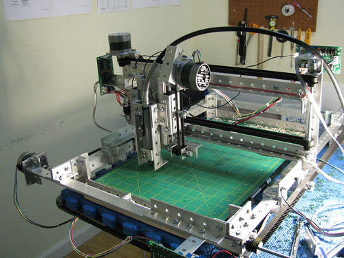
Here’s the setup. I think that qualifies as the most complicated breadboard I’ve done; there are two 16-pin shift registers, 12 pins from the connector, and then 7 pins out to the arduino.

Testing the shift register for real

Now that I can read data – theoretically – I want to track what data the machine is sending over the bus. The simplest thing to do would be to just add a call to Serial.println() after the data is read.

But the serial port is *slow*. Too slow to be able to capture sequential values of data.  Instead, I allocate 128 bytes for the row and column, capture that many chunks of data, and turn off the capture while the main loop writes the data out the serial port. And then repeat.

I build the code, download, and I start getting data. Lots of data, since the pinball is in attract mode (lots of flashing lights), and that’s not what I need. I flip the machine into single lamp test mode, capture data, and see the following:

      Row       Column
11111110 11111110
11111111 11111101
11111111 11111011
11111111 11110111
11111111 11101111
11111111 11011111
11111111 10111111
11111111 01111111

That is precisely what I had hoped for. The system is walking sequentially through all of the bits in the column byte, and it is setting the row byte values appropriately. It’s not quite as simple as this, because the lamp is flashing on and off, but it’s close.

I did note that the C# code that I wrote has the bitness wrong for the columns, so I went back and fixed it so that both are enabled with a zero bit.

Integrate the lamp matrix code

Finally, I can integrate the C# code I wrote. I do a quick transform into C++ code, and hook it up. I run into a couple of issues, but it mostly goes clean. But the data has a bunch of junk in it; it doesn’t look like the data I was getting before. Thirty minutes yields no clues until I look up and realize the the weight of the Arduino and analyzer had pulled the connector out of the breadboard. A bit of strategically-deployed blue tape holds it in place, and the data comes out fine.

Okay, except for one thing; it’s in row-major form rather than column-major form, but that’s a quick change.

Communicating the state out

To correctly identify the state of the lights, I need to be able to detect three states:

  • Off
  • On
  • Flashing

The way I do this is to allocate a byte for each lamp, and then decode 128 separate chunks of data. Since it takes 8 chunks to cover the whole matrix, this gives us 16 samples for each lamp. That gives us a zero if the lamp is off, a 16 if the lamp is on, and something in between if it is flashing.

To communicate it out we create a 64-character string by adding the value for each lamp to the character ‘0’, so our range is 0123456789:;<=>?@  (I considered a modified hex with 0-G, but that would be a little harder and slower to create), and then send the values out the serial port.

But, as usual, it’s a wee bit more complicated. I don’t have time in the interrupt handler to send that whole string over the serial port, so instead I copy a snapshot of the string and have the main loop write it across the serial port.

And, at this point, this part of the project is all working; I get consistent strings that give me the state of all the bulbs in the machine.

Next steps

Now, I need to convert it from a mess of spaghetti wiring into something better. I have a few options:

  1. A hand-wired Arduino shield
  2. A custom pc board arduino shield
  3. A “Pinduino” design that takes the Arduino Uno reference design, deletes what I don’t need, and adds in the connector and the shift register

#1 and #2 seems the easiest. I might do #3 at some point.

Oh, and there’s the next section, the whole reason I built this thing. But that’s the subject for another post.


Decoding Pinball Bus Signals Part 4

After spending a few weeks working on the software, it’s time to get back to the hardware. My first task is to hook up the arduino and see if I can reliably trigger off the interrupts.

The answer to that question is yes; setting the trigger on “FALLING” works reliably. But I came across the following behavior that is a big puzzling:

These are the row and column strobes. On the left, you can see the top strobe happens first, and then the bottom strobe. If I zoom in, I can see that they occur when data is present on the bus (bus signals not shown). Just as it should be.

But what is going on with the signals on the right? Here’s a bigger picture:

This is weird; first we see a column/row strobe with some crappy looking bus data, and then a row/column strobe with some good looking bus data. This would seem to indicate that part of the time, the CPU sends data and then sends different data soon after, and other times it just sends the data. The hardware in the machine won’t care; the time that the first data is present is so short that it should not affect the behavior of the lights in a noticeable way.

But is this what is really going on, or is it a glitch in my logic analyzer? Time to find out…

BTW, the big square wave in the middle is an output from the Arduino. An interrupt service routine is hooked up to the bottom signal on the trace, and the lag between the negative edge on the strobe and the positive edge on the arduino trace is the time it takes the interrupt to happen + the time it takes to turn on a pin. So, it appear the decision not to do this purely in software on the arduino is a good one.

To figure out what is going on, I wrote an arduino program:

void setup() {
  pinMode(0, INPUT);
  pinMode(1, INPUT);
  
  attachInterrupt(0, rowDataHandler, FALLING);      // pin 2
  attachInterrupt(1, columnDataHandler, FALLING);   // pin 3
 
  Serial.begin(9600);
}

unsigned long startTime = 0;
const int ArraySize = 128;
unsigned long rowTimes[ArraySize];
unsigned long columnTimes[ArraySize];
int rowIndex = 0;
int columnIndex = 0;

void rowDataHandler()
{
  digitalWrite(8, HIGH);
  if (rowIndex < ArraySize)
  {
    rowTimes[rowIndex] = micros();
    rowIndex++;
  }
  digitalWrite(8, LOW);
}

void columnDataHandler()
{
  digitalWrite(9, LOW);
  if (columnIndex < ArraySize)
  {
    columnTimes[columnIndex] = micros();
    columnIndex++;
  }
  digitalWrite(9, LOW);
}

// the loop function runs over and over again forever
void loop() {
 
  while (rowIndex < ArraySize && columnIndex < ArraySize)
  {
    Serial.print(".");
  }
  Serial.println();

  Serial.println("Times");
  for (int i = 0; i < ArraySize; i++)
  {
    Serial.print(rowTimes[i] – startTime);
    Serial.print(",");
    Serial.println(columnTimes[i] – startTime);
  }

  Serial.println();

  startTime = micros();
  rowIndex = 0;
  columnIndex = 0;
}

Basically, it sets up interrupt handlers for both row and column strobes and then starts saving the time when the interrupt occurs. When it has collected 128 of each, it stops collecting them, and the main loop sends them out over the serial port. Then the process repeats itself.

I took the data and pulled it into Excel for analysis. This is the delta time between interrupts, all times are in microseconds.

Row Delta Col Delta
   
2064 2112
44 44
1992 1992
44 44
2048 2044
44 44
1952 1956
44 44
2000 2000
44 44
2008 2008
44 44
2000 1996
44 44
1996 2000
44 44
2000 1956
2048 2048
2056 2056
2052 2096
44 44
1988 1984
44 44
2008 2008
44 44
1996 1996
44 44
2000 2000
44 44
2000 2004

There are times with a double interrupt, and other times that only have a single. Sometimes the row interrupt comes first, sometimes the column one comes. The period is right around 2 mS, so the frequency is pretty close to 500 Hz; exactly what I had measured before. The time period between the first one and the second is either 44 or 48 uS; I think the difference depends on the ordering.

The ratio of the two time periods is 44/2000, or just about 2%. Based on my extensive experience dimming lights by microcontroller, I can tell you that 2% isn’t really a noticeable difference in how a light looks; you *might* be able to detect the difference between 98% and 100% brightness in a controlled setting, but it would be hard to do. I’m confident that you can’t tell the difference between 0% and 2%, because on a incandescent light, 2% is just off.

I did a little graph in Excel that looked pretty much exactly like the logic analyzer image, so I won’t share it here.


How to deal with this? Well, I think it will actually turn out to be pretty simple. Instead of doing work directly off of the row or column interrupts, I will set up a short timer interrupt (let’s say 100 uS or so) whenever the row/column interrupt fires. That will be updated by any new strobes that occur before the timer expires, so the effect will be that the timer interrupt will be serviced a short time after the last row/column strobe.


Pages:1...12131415161718...35