Browsing posts in: EagleDecorations

WS2811 expander part 4: Boards and Parts!

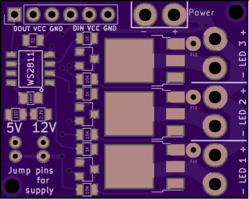
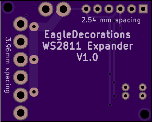
After a bit of waiting, the boards showed up from OSHPark. they looked fine as far as I could tell.

I had all the other parts to do a board, but I needed a paste stencil. I went into pcbnew, chose File->Export, and then chose to export the F.Mask (ie solder mask) layer to a SVG. I cleaned it up a bit to remove non-pad elements, went out to the laser cutter and cut a stencil out of 4 mil mylar:

IMG_9495

Everything looked pretty good; there was good alignment between the board and the stencil. The spacing between the pads looked a little tight, but it’s a fairly fine pitched board, so it was mostly what I expected.

I carefully aligned the stencil and taped it on, got the solder paste out of the fridge, and applied it. Pulled up the stencil and it looked crappy, scraped it off, did it again, and got something that looked serviceable though there was more paste than I expected. Hmm.

Got out the components:

  • 1 WS2811
  • 1 33 ohm resistor
  • 1 2.7k ohm resistor
  • 6 10k ohm resistors
  • 3 1k ohm resistors
  • 3 NPN transistors
  • 3 MOSFETS
  • 1 100nF capacitor

and it took about 5 minutes to do the placement. Here’s the result:

IMG_9496

I didn’t look at the picture at the time, but that’s a *lot* of solder paste.

Into my reflow oven (Controleo 3 driving a B&D toaster oven), let it cycle, seemed fine, here’s the board:

IMG_9499

Not my best work. Frankly, it’s a mess; there are obvious places where there is no solder, and obvious pins that are bridged together. I spent about 15 minutes with my VOM testing for continuity and there were 3 solder bridges and 7 unconnected section.

Something clearly went wrong. And I went back to PCBNew and it was *really* obvious.

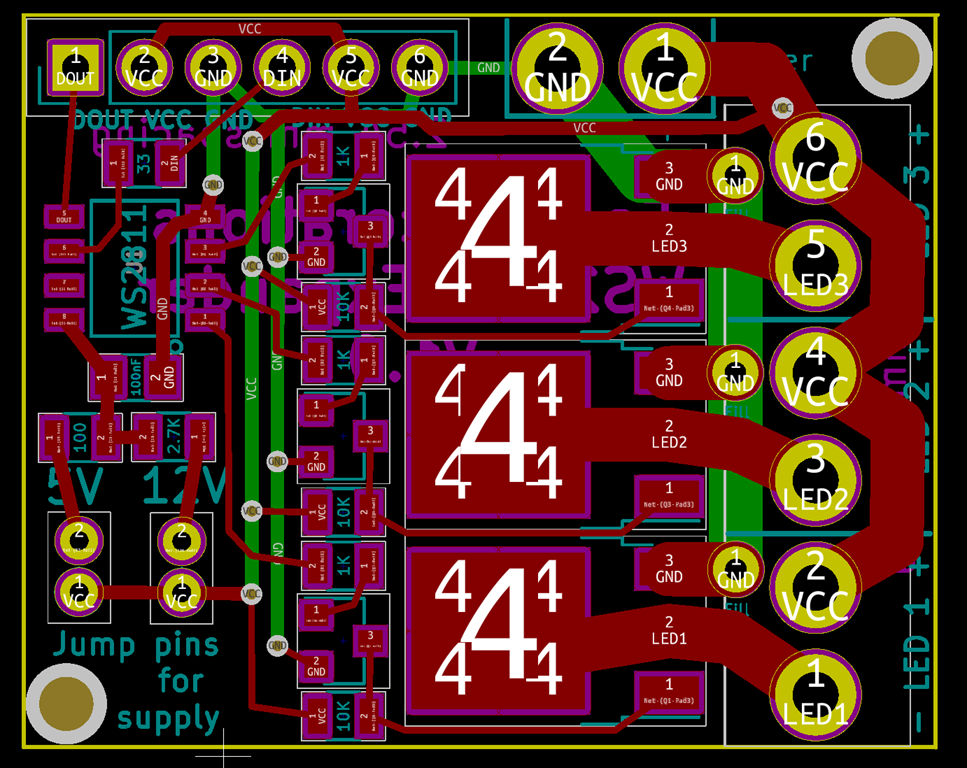
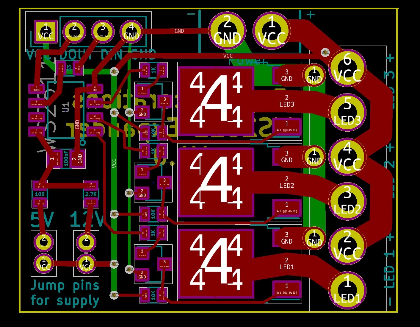
The layer you should choose for your stencil is F.Paste, not F.Mask. Here are the two next to each other (Mask left, Paste right):

imageimage

The Mask layer sizes are positively giant compared to the paste ones. So, what happens if you use the Mask layer is that you have:

  • A *lot* more paste on the board, especially the small pads which must have double the amount
  • Solder paste with much reduced clearances.

What that means in reality is that when you put the components on, it squishes the solder paste together and connects pads that shouldn’t be connect. And then when you head it up, you either get bridges or one of the pads wins and sucks all the paste away from the other pad (how it wins isn’t clear, but it is clear that the huge MOSFET pads pulled all of the paste from the transistors next door).

This makes me feel stupid, but it is actually quite good news; it means that the design is fine and I just need to remake a stencil with the correct layer.

Anyway, after a lot more rework than I had expected, I ended up with this:

IMG_9500

It’s still an ugly board, but does it work?

Well, I hooked up 5V, GND, and data in to one of my test rigs and a LED to the LED outputs.

And it works; the LED is on when I expect it to be on and off when I expect it to be off. All three outputs are fine.

The next test will be some testing to see how it fares with switching high current. And I’ll probably want to make another one using the correct stencil and hook it up for 12V operation to verify that.


New kit: LED Candy Cane part 1

My first kit – the Dodecahedral Light Engine – has been selling about as well as I expected a very hard to construct project with limited usages to sell, which is not very well. I primarily did it because I was going to do them anyway for my decoration project and wanted a project I could learn on.

I’ve just started working on my second kit, which is going to be a lot easier to build, cheaper, and more widely useful.

One of my favorite displays is a “tree of lights”, which is a tree with custom LED ornaments on it:

The ornaments are made of small sheets of plexiglass with high-power LEDs inserted into the holes, wired up, and waterproofed.

They are really bright; note in the photo that all of the dim lights are normal brightness LEDs, and even at that level the ornaments overpower the camera sensor. They are bright enough that – and I am not making this up – they cast a shadow about 50 feet away when they were at full brightness, so I dialed them back a little in brightness.

These ones are driven directly from 120VAC as that is what the controller provides.

What I want from this project.

  1. A fun, easy-to-assembly ornament
  2. The ability to run off of 5V or 12V (*maybe* 120VAC with a big disclaimer that you shouldn’t really do it)
  3. Tunable brightness
  4. The ability to drive them as WS2811 nodes (see my WS2811 expander posts…)
  5. A frame/armature that is easy to produce automatically (the originals were done with a 5mm end mill in a drill press and took a *long* time).


WS2811 expander part 3: PCB Revisions again…

More revisions.

I posted the design to /r/PrintedCircuitBoard, and of the comments said:

“Do you need pullups on the outputs of WS2811?”

And of course, I was confident the answer was “no”. For about 5 seconds. And then I measured the WS2811 I have in my breadboard; it gave a nice solid sink when it was on, and when it was off, just a fraction of a volt. Clearly not up to sourcing current to the NPN transistor.

The most likely explanation is that it’s an open collector output:

The collector on the output transistor is just left hanging – it’s only collected to the external pin. The voltage on an open collector can float up above the internal voltage of the IC as long as you don’t exceed the maximum voltage of the transistor

Open collectors are really useful if you want to have a bus architecture with multiple components able to pull the bus low, or if you aren’t sure what voltage of the output is going to be. Since the WS2811 can be used to drive LEDs tied to either 5V or 12V, it makes perfect sense. And it is confirmed by the internets.

Which means that the circuit needs to get a tiny bit more complicated:

image

Another pullup resistor is added to the mix. Really not a problem from the cost and assembly perspective as the design goes from 9 resistors to 12 resistors.

But, can I fit it in the current board layout without making it bigger?

I should probably add a parenthetical note here that says it’s often easier to go with a bigger layout, and in fact if you are going to hand solder a board, you *should* go with a bigger layout. Though I’m not sure how practical it is to solder the MOSFETS by hand since the base pad is so big…

Anyway, here’s what the board looked like before:

I need to put a resistor between each of the traces that head from the WS2811 over to the transistors. Hmm.

I initially just tried to fit them in there, and with a big of rerouting, I was able to make it fit. Technically.

Then I decided that it would be a lot easier if I moved the vertical ground trace underneath the transistors and used that to provide the ground connection to the transistors. That meant I could move the VCC vias around more easily, and could do the following:

image

The fit in reasonably well.

I *think* it’s ready to order the first version of the board, but there’s one more step. I now have on hand the WS2811 ICs and both kinds of transistors. So, I printed out a design with the copper layers shown, and did a test to see if the components really fit on the board.

image

That shows the WS2811 on the left, the MOSFET on the right, one of the NPN transistors and then a tiny 0805 10K resistor at the top. Everything looks like it will fit fine.

I ordered 3 boards for $7.10 from Oshpark, which is my usual supplier for prototype boards if they are small.


WS2811 expander part 2: PCB Revisions

I’ve done quite a few improvements on the board. Let’s look at before and after:

imageimage

My usual flow is to do some changes, and then load the board into OSHPark and see how it previews. And then make changes.

I’ve probably redone the majority of the traces on the board. The big changes are:

  1. I replaced the 0603 resistors with 0805. I’m going to do the components by hand, and the larger resistors are easier to place. And I have a set of 0805s sitting in my drawer.
  2. I realized that I hadn’t planned for chaining together more than one board. After 3 or four revisions, I settled on a single 1×6 header to hold both sections. You can either use two 1×3 headers or one 1×6.
  3. The big headers for power and the LED output were bigger but not a standard connector, since I just wanted them to be easier to solder to. That was stupid. They are now spaced to use standard 3.96 mm spacing (Molex KK line if you want branded stuff), so you can either solder or use a connector. This made the board just slightly taller.
  4. The transistors and resistors have been moved, aligned, spindled, and mutilated.
  5. Added holes for mounting, though it’s probably not needed with a board this small. But I had space.
  6. Added some more labels.

Updated schematic

image

Board shots

I’m thinking this is probably good enough to get my prototype versions built.


WS2811 expander

I’m starting a new decorations project that will involve a fair number of standard LEDs, but not addressable ones. I have a few different use scenarios:

  1. Plug into a standard USB power supply.
  2. Power directly with 120 VAC.
  3. Power either with 5V or 12V and have an easily way to control brightness…

The first two are just wiring, but the third needs something more. My target market is quite used to using WS2812 addressable LEDs, so I’m going to build something that works in that environment.

Quick requirements list:

  1. Runs on 5V or 12V.
  2. Uses WS2812 protocol.
  3. Can drive significant loads (at least 10 amps).
  4. Small and cheap

The second requirement is pretty simple; you can buy the WS2811, which works exactly the same way as the WS2812 lights but is in a separate package. And it very conveniently has a little internal power supply that can use 5V or 12V by changing the value of one resistor. Here’s a typical 5V circuit:

image

Looks very nice, and almost does what I want, except that it’s designed to only sink 18.5 mA, which is quite a bit less than my 10 amp goal. I don’t strictly have a use for 10 amps right now, but I will likely need at least 1 amp for some uses.

So, I’m going to lean on the IRLR7821PbF MOSFET that I used in my backyard controller, which it looks like I can get for about $0.14 each. It’s pretty easy to use:

image

I will just drive the gate of the MOSFET with the output of the WS2811, and when the MOSFET turns on, it will pull the LED1 line low, turning on the LED.

Except… the WS2811 outputs are active low, and the MOSFET in this arrangement is active high. So

image

We add an NPN transistor. If the input is low, the transistor is off and the gate on the MOSFET is pulled high by the 10K resistor. If the input is high, the transistor is on, the gate is pulled low, and the MOSFET is off.

That will be duplicated for all three channels, and we end up with the following:

image

R9 and R10 are really just empty holes; you bridge R9 with wire if you want to use 5V and R10 if you want to use 12V.

I unfortunately generally forget to take snapshots during PCB design, so here’s the V1 state:

image

The MOSFETs have lots of 4s on them – I don’t know why – and to the left are the bipolar transistors and the resistors required for that part of the circuit.

The power input holes and the LED holes are designed to use Molex KK 396 headers and connectors so you can either use those or hand wire.

The lower left shows the jumper locations to set voltage.

All resistors are 0603 sized; that makes them compact but still relatively easy to populate.

The only weirdness are the three through-holes next to the LED terminals. I need to tie that backside ground trace to the frontside MOSFET terminal, but I was having trouble fitting enough vias to carry the current. Instead, I just used the through holes, which will be filled with solder and therefore be able to carry plenty of current.

The board is about 40mm x 28mm in size. I might jump up to 0805 resistors to make it a little easier to fabricate.

Before I send it off to be fabricated, I need to have the transistors in hand so I can verify the layout works.


Connecting the Eagle Controller to a WS2812 strip

To connect the Eagle controller is simple; there are only three connections to make:

image

The following connections need to be made:

  1. The black wire from the strip (or globe) should be connected to the ground pin
  2. The red wire should be connected to the 5V (5 volt) pin
  3. The data wire (purple from the globe) should be connected to the RX pin.

This will be enough for the controller to work if powered through the USB mini jack. This is fine for testing, but has several drawbacks:

  1. Each WS2812 LED will draw 60 mA of current if it is full bright. There are 33 on the globe, which means that full white will draw 60 * 33 = 1980 mA = 2 amps. The USB connector will not be able to supply that amount of power, so you will not get full brightness.
  2. The Eagle controller has a diode so that external power will not power the USB jack. This means that instead of getting 5V to the strip, you get about 4.4 volts to the strip. It also means that there is a lot of power being dissipated by that diode, and it will get *hot*; hot enough that it or other components on the board may fail.

To avoid these issues and enable full brightness, you need an external 5V power supply that can supply sufficient current. It can be connected to the 5 volt and ground connections.

Using the connection board

Newer versions of the controller ship with a small adapter board to make these connections easier.

image

We will start by soldering a male header to the series of pins on the right side of the controller with the pins sticking out underneath. You can get by with just using pins for 5V, ground, and RX, but there’s no harm in soldering all 8 pins. Here’s how I do it:

image

Place the header pins into a solderless breadboard with the appropriate spacing. We put pins in on both sides so the board will sit level, but we are only going to be soldering the ones at the top.

This step may have been done for testing purposes.

It should look like this when the pins are soldered:

image

Now, we need to solder a female header to the adapter board:

image

The header should stick out above the board in this orientation. To do the soldering, I balance the board on the female header and use the other strip of female header to hold the board level:

image

Solder all 8 pins across the top.

image

This is the controller with the male header and the adapter board with the female header. The male header simply plugs into the female header.

image

The wires to the LEDs are then connected to the upper 3 terminals on the adapter board, and the 5V power supply is connected to the lower two terminals.

Compact option

If the controller and the adapter are too thick, there is an option that is thinner:

image

In this option, the female header is omitted and the adapter board is soldered directly to the male header pins.

If you are really tight for space, you can solder the male header, remove the black plastic that separates the pins, and then slide the adapter board right next to the controller.


DLE (Globes of Fire) Part 5 – First Board!

When a new telescope is completed, one of the big milestones is known as “first light” – the first time that the telescope is used as it is intended.

Now that I am the proud owner of a reflow oven – a modified Black & Decker toaster oven fitted with Whizoo’s Controleo3 reflow oven kit – and I have a new version of my boards back – it’s time to think about how to build these things in a reasonable way.

The plan is obviously to switch from hand-soldering to reflow. To do that, the first thing that I need is a stencil that I can use to apply solder paste. Thankfully, kicad makes this really easy; you can modify the solder pad tolerances in the program, and the pcb editor can write out SVG files (thanks to Rheingold Heavy for this post). If I have the pads, I can easily cut a stencil, likely out of mylar because it’s a bit cheaper than Kapton is.

That would give me a way to do a single board if I could hand-align it closely enough. But each of the globes needs 12 of these boards, and hand-aligning is a pain.

So… what my real plan to do is to cut holes in a piece of hardboard (or cardboard) that will hold a number of the boards (12 or 24) and then a matching stencil. If I align the stencil one, then I can put solder paste on all of them.

IMG_9223

So, here’s the test. I took the pad svg and the board edge svg, joined them in inkscape and then cut them on the glowforge. As you can see, the boards fit perfectly into the cutouts, and the solder pads cut correctly. Next I will need to do a better version of this, with different colors for the pads and board edge so I can turn them off and off when laser cutting. I’m also probably going to cut holes for some posts that will give me registration between the board with cutouts and the stencil.

You can also see the first two boards that ran through the reflow oven. I did the solder paste without a stencil and I also skipped baking the LEDs since they showed up in a factory-sealed pack and have been sealed since, and both boards came out fine. And a 10 minute reflow cycle is a lot quicker than hand soldering…


Provisioning and using the ESP8266 controller

The ESP8266 controller is preprogrammed with the ability to connect to your local wifi network and be remotely controlled.

Provisioning

Initially, the controller does not know how to connect to your network, so it sets up its own network. Here is how to set it up:

  • Using your phone/laptop/tablet, connect to the network named something like “EDP_1002170403”. The password is the same as name of the node.
  • One you are connected, open up your browser and navigate to http://192.168.4.1. That should enter the provisioning page. Enter the SSID of your wireless network and the password, and click on connect.
  • If everything is working correctly, that will connect to your wireless network. You can find out the IP address by looking for the “EDP_…” name in your browser’s host table, or you can hook the esp board up to your computer and watch what it writes out the serial port when it boots.
  • Controlling via http

    You can control the LEDs via http by sending textual commands to controller. The format looks like this:

    http://[ip address]/message?content=[message]

    Controlling vs UDP

    If you want realtime control of the LEDs, http may have too much latency, which may result in unexpected pauses. The controller also supports communicating through UDP.

    To connect via UDP, use the same IP address and pass commands directly. The internal controller code runs at 100 Hz; if you drive with UDP messages at 60 Hz everything should just work great.

    Supported Messages

    All commands are three letters long, followed by another character (the examples use an underscore (“_”), followed by numeric parameters.

    The following commands are supported:

    Alternate

    Alternate between two colors.

    alt_r1,g1,b1,r2,g2,b2,time

    r1, g1, b1: the rgb values (0,255) for the first color (0-255)
    r2, b2, b2: the rgb values for the second color
    time: the time for each color

    Example: alt_0,100,000,000,000,000,250

    Blend to

    Blend from the current color to a specified color

    rgb_r,g,b,time

    r, g, b: the rgb values (0,255) for the new color
    time: the time for the blend

    Example: rgb_255,255,255,1000

    Color rotate

    Rotate through a bunch of different colors.

    col_speed,brightness

    speed: the speed of the rotate
    brightness: The brightness of the colors

    Example: col_5000,200

    Flash decay

    fdc_decay,min,max

    decay: the speed of the decay
    min: the minimum pause before the next flash
    max: the maximum pause before the next flash

    Example: fdcx250,10,500

    Full control

    Full control is used to control the color of all the leds directly.

    ind_chunk,data-bytes

    chunk: the number of leds to apply each set of data to.
    data-bytes: colors express as two digit HEX values in the format RRGGBB

    Example: ind_011,000044440000004400

    Each color in data-bytes will apply to 11 LEDs. The data-bytes contain 3 color values:

    000044 – a blue value
    440000 – a red value
    000044 – a green value

    Save

    Save the current animation so that it will use that animation when rebooting.

    s

    Set pixel count

    Set the number of pixels that the controller will use. This will result in a reboot of the controller.

    n_count

    count: the number of pixels

    Example: n_13


    Pages:12