
I’ve finished my landscape lighting project, and thought I’d share how it came out.
I had a few requirements:
- I wanted to be able to turn on and off the lights from out where the lights were (some 150′ from the house) so we could have light when we showed up at night.
- I wanted the lights to turn off automatically after 2 hours if they were accidentally left turned on.
My first design was pretty simple – I would put pushbuttons out with the lights and do a simple program for an AVR microcontroller to detect the pushbuttons and handle turning on and off the lights. That hit a couple of snags.
The first was a physical one – putting physical pushbuttons out meant that I’d have to run about 700’ of signal wire, build waterproof boxes to hold the pushbuttons, mount them on the trees, etc. That was a fair bit of extra work, and not the fun kind.
The second was a bigger problem. Sensing physical pushbuttons was insufficiently challenging and interesting.
So, a V2 design was born. I had been looking for an excuse to do something with some of xbee radio modems, and I decided to use the xbee pro modems for the project, since they are higher power and longer range. These are really cool devices which, in their default mode, act like a virtual serial cable. You send characters into the modem at one end, and the same characters come out the other end. It will do this at up to 250kbps and a maximum distance of a mile (your mileage may vary. Actual mileage will probably be less). You can do a lot more sophisticated stuff with it (meshes, repeaters, etc.) in the advanced modes as well. The modems also have some built-in analog->digital conversion and digital I/O circuitry built in, but since you need a microcontroller to drive it I don’t see a ton of use for that in most applications (though it might be useful in some pc connected applications).
If you are building something that is xbee-based, I highly recommend getting one of the usb adapter boards like the one from sparkfun. It is really useful to send command from the PC, and you can use putstring to write debugging information back to the PC.
After a fair bit of experimentation, I ended up with the following scheme:
The base station sends out a status heartbeat every 1/10th of a second. It also handles the status led, any button presses on the wired remote, and timekeeping. Separately, it also handles any on/off command that come in over the xbee.
The remote receives the status heartbeat, and uses that to turn on the link led (lighted whenever the status heartbeat is received), and set the light status either on or off based on the current status of the lights.
Time for some pictures. Click on the picture for a bigger version that has the parts identified.
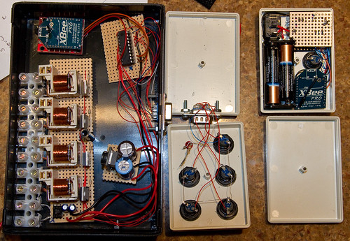
The big black box on the left is the base station. To the right of it is the wired remote, and on the far right is the wireless remote.
I should note that everything here is hand-wired. It’s not what you would call neat, but it is simple to do and functional. The thin wire that you see is 30 gauge wire wrap wire, which is more than enough to carry digital signals. When I’m hooking it to discrete components (caps, resistors, leds, etc.) I use my cheap wire-wrap tool and wrap the wire around 3 or 4 turns, and then solder it. This makes it easy to hook the wire up so it doesn’t come off while I solder it.
We’ll start with base station.
In the upper left is the xbee pro radio modem sitting on top of a sparkfun adapter. The sparkfun adapter gives you easy access to all the pins, but the only reason I used it here was because it does the conversion between the 5v that the attiny is using and the 3v that the xbee wants. I could have done it all at 3v, but I didn’t think about that option until I had already put in my last order for parts in.
Below that is the relay board. It has 4 channels (I added individual channels addressable from the base station). Each channel features a 5V relay that switch the 12VAC that the lights use. I’m not a big fan of relays – for AC either using solid-state relays or triacs is generally simpler, but 12VAC is an odd beast and nobody builds a lot of designs for that, so I went with the relays. The downside of the relays is that they require a fair bit of current – about 200mA each. That will cause a bit of an issue later. Each relay is driven by a dedicated transistor, since there’s no way the ATTiny can push 800mA through it. The transistors are NPN power transistors in TO220 packages, which are a bit more rugged than the small ones in case I needed to dissipate a bit more heat. The relay board is the the least optimal part of the design, since it requires a 5V power supply that can put out a lot of current. A better approach would have been to use relays with 12VAC coils, and then drive the coils with some small triacs – that would have reduced the power supply requirements way down. If I had built that power supply up front and tested it driving 4 relays, I would have found that out, but I drove it from my bench supply instead. At the bottom of the relay board is where the 7805-based power supply lived originally, which worked but put out way too much heat.
To the left of the relay board is the terminal strip to connect the lights, and the 12VAC input at the bottom. This sticks through a slot cut in the side of the box.
To the right of the relay board is the switching power supply. I could have built one myself using the popular lm7525, but to make things simpler I ordered a prebuilt one. There’s a hefty 2200uF capacitor on the input from the board to smooth out the rectified 12V from the full-wave bridge on the relay board, and then a 470uF capacitor to smooth the output of the 7525. That gives me the power I need to drive the relays without too much heat.
Finally, on the right side is a DB9 (aka “old-school serial portâ€) connector. In my current installation, the base station will live close to the wired switches, but will eventually move to an outbuilding. At that point I can just pull some cat5 wire and add connectors to hook the base to the wired remote. To the right is the wired remote, which couldn’t be simpler – there are 5 pushbuttons and a status led, some wire, and a DB9 connector.
On the far right is the wireless remote.
In the upper left is the power switch. I went with a hardwired switch because the remote will likely rattle around in a glove compartment, and I was worried that any button-press approach would be prone to accidental activation. Below the switch is two AAA batteries, which gives me the 3V that the remote runs on. To the right of that is the xbee pro module, with 4 wires hooked to it – +3V, ground, transmit, and receive. Above that is the on/off pushbutton. Finally, lurking at the top-right is the bottom of the board that holds the attiny2313 – it’s upside down because the status LEDs are underneath the board on one end, and if it was the other way it would be likely to short out.
Here are the assembled remotes:
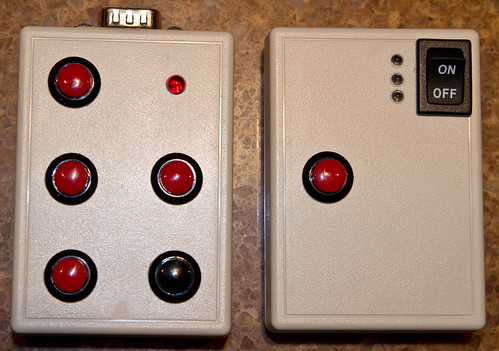
On the left one, we have the three separate channels on the left, all on/all off on the right, and status at the top. The wireless remote has the pushbutton, on/off switch, and 3 status leds. The top led is power – it is on for 1/10th of a second, off for 9/10ths of a second. The middle led is link status (on = linked), and the bottom is the light status (on or off, in case you can’t actually see the lights).
So, what do you think ?