I sell a small WS2811 expander board on Tindie:
/i/362101/products/2019-05-01T00%3A32%3A50.588Z-IMG_7057.jpg)
It’s not a particularly complex board, but it still needs to be tested, and at minimum that test requires 9 connections to the board. For the prototypes I just soldered wires on, but for the ones I sell that would not be a good idea, and it would also be a fair bit of extra work.
I decided to build a pogo-pin test jig, and since the approach I came up with was different than the other approaches I’ve seen I thought it would be worth sharing. I’m going to be targeting my laser cutter for fabrication, though I could have chosen to use my 3D printer instead.
Pin design and layout
I’m going to be using Kicad for my examples here; if you use something different, you’ll need to figure out how to do some operations ourselves.
Here’s the starting design:
For testing, I need to provide connections to a subset of the all of the headers. I’m going to do the design for all of the headers and then just populate the ones that I need. For many boards, you would have test pads that are unpopulated as the targets for your testing.
I need a way to get this into a format I can use with my laser cutter, and SVG is the one I’d like. Kicad can export to SVG just fine; you use the Gerber export and choose “SVG” as the format (no, it doesn’t really make a lot of sense). I’ll be using the pins to connect to the copper, so I’m going after the copper layer.
Once it’s exported, I can open it up in Inkscape for editing:
I’m going to clean this up to get rid of all the parts that I don’t need. In some cases, the components are grouped and I need to ungroup them.
What I want to do is put a pogo pin at the middle of each of these. These are the pogo pins that I’m using:
They are spec’d to have 1mm shafts and they’re quite close to that, so we’ll plan our design using that.
At this point, we need to account for one of the things that Inkscape does. The UI allows you to set the size of a circle, but the size that you set is the outer side of the circle, and that includes the stroke width. If your stroke width is 0.25mm and you set the circle to 1mm, the actual circle will only be 0.5mm.
This confused me for a while when I did my first prototype. And then it confused me again when I did this version. The fix is to set the stroke width to 0 – or something very close to 0 – and use a filled circle instead.
Here’s a picture of a pad and a 1mm red circle I want to center inside of it:
I need to get that red circle centered inside the pad. Because of the way Inkscape works, you need to start with the small circle on the lower left. I don’t know why. Then do the following operations:
- Drag select both objects.
- Choose “align top”
- Choose “align right”
- That should move only the red circle.
- Align center on the horizontal axis
- Align center on the vertical axis.
To select the circles I need to drag a region; it doesn’t work trying to select the object. I don’t know why.
That gives us the following:
Eventually, I will want one of those for every pin. But I need to do some test sizing first.
The beam on a laser cutter is pretty thin, but it still has some width. That means if I cut out a 1.0mm circle, I’ll get one that is just a bit bigger than that, and the pins will be loose.
I’m going to use the row of 6 pads at the top for test sizing.
You can’t tell from the picture, but these are sized 1.0 mm, 0.975 mm, 0.950 mm, 0.925 mm, 0.900 mm, and 0.875 mm.
Off to the laser cutter!
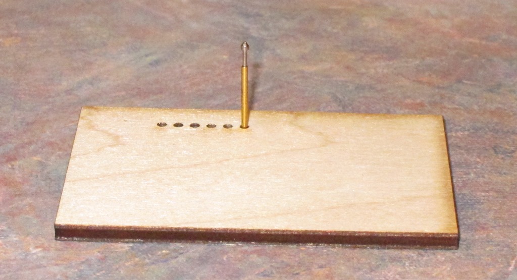
The test fixture cut out of 0.1” (2.6mm) maple plywood.
The 0.875mm hole is the only one that is close; it’s a tiny bit snug in the middle (the laser beam is shaped like a very tall “X”, so the hole is thinnest at the focus point in the middle and a little bigger at the top and bottom).
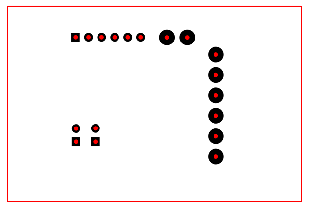
Based on the step in sizing between holes, I’m going to size them all to 0.85 mm.
That’s the completed design. In my laser cutter (a GlowForge), it groups the elements by color, so it’s easy for me to tell it to cut the red circles and not the black pads. If you want to simplify the cutting part, you might want to delete the pads.
Back to the cutter.
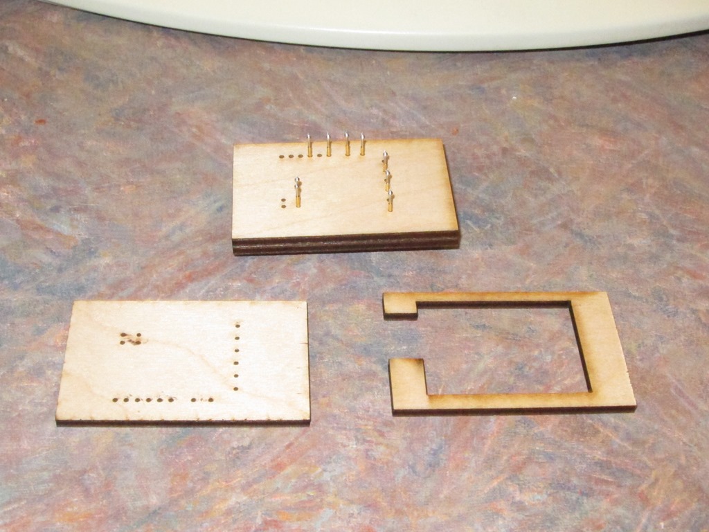
I cut 3 identical plates plus a spacer. The stack will have two plates with holes, then the spacer level where the wires will be soldered to the pins and finally a plate at back. The wires will all come out through the spacer holes on the left. It’s hard to tell from the picture, but the pins are inserted so that they stick out the back enough for the bottom of the pin to be flush when the spacer and bottom plate are added.
Oh, and that lower-left piece is upside down…
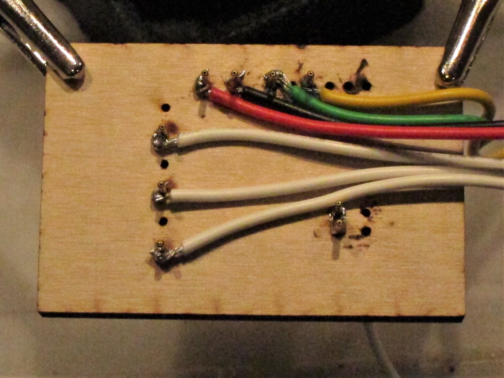
Next is hooking up the test wires. There are 22 pin holes, but two of them need only to be bridged and seven connected with wires for testing.
That’s a rather poor picture of the wires attached to the pogo pins. After they are all soldered on, the back piece goes on and then I taped it together with blue tape so the pieces are apart.
That would normally be the last step, but the high-current pins on this board are set up using 3.96mm headers instead of the 2.54mm that my pogo pins are designed for, so those pins just go right through the bulbs. With a little bit of play using a soldering iron, you can get a blob of solder on each of those pins and then it will work fine.
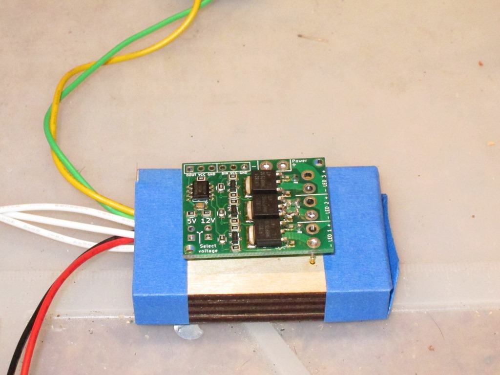
Here’s the completed tester with a board just sitting on it.
The yellow and green wires come from an ESP8266 that I use to drive it, the red and black are 12V power from a repurposed XBox 360 power supply, and then the white wires are the grounds for the loads (the board provides both positive and ground for each LED, but I only need the grounds to do the testing).
I made a quick video showing the tester in action.
MVI_0093 from Eric Gunnerson on Vimeo.


So, concerning Inkscape and alignment, if you open the alignment tool tab, you can see that it allows you to align on first selected or last selected, along with other options. That is how it decides which object is the reference (and does not move). Then you can manually select multiple objects by holding shift and left clicking them in order.
Hi Eric, very cool project. I’m studying electrical engineering at the moment so i think this will be very useful in the future.
In my past experience with Inkscape and lasercutting i’ve experienced the same problem you’ve described where the outside dimensions of a shape also include the line thickness.
There is actually a solution to this. If you go to “Preferences” (Edit >> Preferences or Shift+Ctrl+P) and select the “Tools” menu, you can choose which bounding box to use. The default is “Visual bounding box” but if you change it to “Geometric bounding box” the problem is solved. Inkscape then excludes the thickness of the lines in the dimensions.