
I got the boards back from OSHPark a while back, and got around to populating them. Though I have access to a real reflow oven, I’ve done boards like this with the heat gun method in the past, so I got out the solder paste, put it on the solder pads, put on the shift registers, and then went out to the garage.
I use an old license plate as a board holder, so the board goes on that.
Real reflow ovens use a time/temperature calibrated curve.
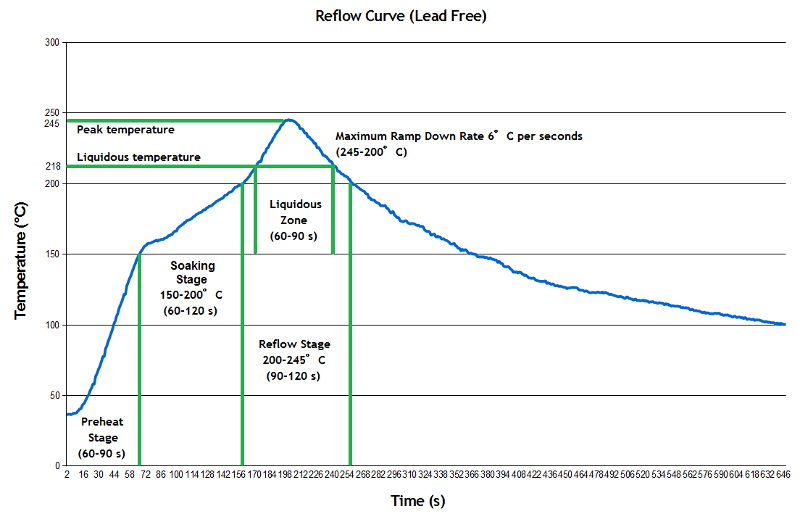
Basically, there’s a long soaking stage to gradually bring all the parts up to temp, a ramp up until the solder melts, and then a cooling-down period. I attempt to duplicate this with the heat gun, though it’s really not very precise.
The hard part with the heat gun is keeping it at a distance where it does not blow the parts around on the board; as the board heats up the flux will start to flow and the chips want to move. A little repositioning with a toothpick fixes that. You keep heating until you see the solder reflow, make sure it’s reflowed around all the parts, and then remove the heat.
And you get this:

The 34-pin connector and the two test point connections were hand soldered. I do need to test the board itself and then hook it up to the pin and see if it works.
Hi,
I’m interested by your pinball lamp matrix decoder, did you succeed ?
I don’t find the complete info on your site , do you have Arduino program and schematic ?
I would like to drive external hardware based on my Williams system 7 board.
Thx
JP