
I have a project in mind for my Twilight Zone, the exact details of which I will reveal later.
To implement the project, I need to detect when specific lights are lit in the machine. I thought of a couple ways of doing it. I could put a light sensor underneath the playfield or I could hook up to the wires that power the lamp. Both are fairly straightforward to do, but they are a bit inelegant, and I’m in the mood do to something more elegant.
So… What if we could read the signals that the CPU sends to the driver board? We could figure out whether any of the lamps is lit with a single connection to the system?
Okay, so, what would that take?
Well, the Twilight Zone uses the WPC architecture, and is driven by a 6809 running at 2 MHz. I don’t know if that’s the bus speed and am too lazy right now to find out, but I’m hoping that I can do what I need with an arduino running at 16 MHz. What do I need to do? Well, that requires a bit of a journey…
The lamp matrix
Pinball machines have a lot of light bulbs, and running an individual wire would be expensive. So, instead of running separate wires, machines use a lamp matrix.
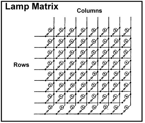
We have 8 rows, and 8 columns. To turn on a light, we drive the column to positive voltage and the row to ground, allowing current to flow. With a bit of code, we can drive them all. Basically, the code looks like this:
- Drive all columns low.
- Drive the rows that we want to light in the first column low.
- Drive the first column high
- Wait, and then repeat steps 1-3 with each additional column.
Digging into my WPC Schematic manual, we find some nice designs about the row and column drivers. What we are interested in is the method that is used to pass the row and column information to the driver board. It turns out it’s pretty simple:
- Both the rows and the columns have a 74LS344 latch connected between the CPU bus and the row/column driver electronics.
- The latches are clocked (ie data is loaded into them) when a line (ROW_STROBE or COL_STROBE) from the CPU is driven high.
So, in concept, what the microcontroller needs to do is pretty simple. First off, we need external interrupts defined and hooked to ROW_STROBE and COLUMN_STROBE. When either of the interrupts fire, we need to quickly grab the value from the data bus. From that, we can tell which lamp is in which state, and pass that information on. I would also like to detect flashing lights, which will require a bit more code.
I bought a small logic analyzer from Seed Studio so that I can eavesdrop on the bus and see what is really going on. That will probably be the subject of the next post.
So, what do you think ?