This guide will describe how to build the Globe of fire. You will need the right tools and good soldering skills to build it successfully.
Please read through the entire guide before you start assembly.
The kit comes with the following parts:
- 12 polygonal face circuit boards, each with 3 WS2812 LEDs already mounted (you will only use 11 of these)
- 1 bottom face with a big hole in it
- Connecting wire that will be used to connect power and a control signal to the globe.
- 4 assembly jibs to hold the polygonal faces at the proper angle
- 1 1/4″ bolt and nut to serve as a base
- 1 stand to hold the completed globe up
- Approximately 60 tiny half-circle wires, used to connect the polygonal faces together.
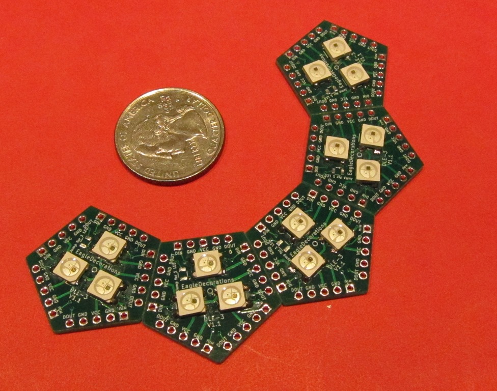
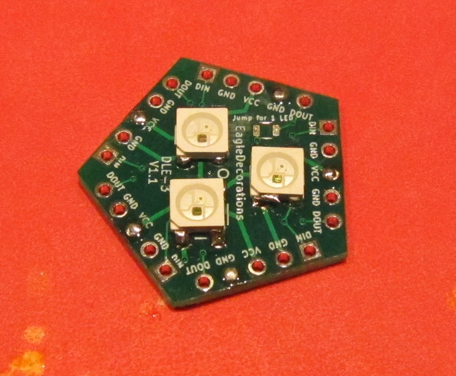
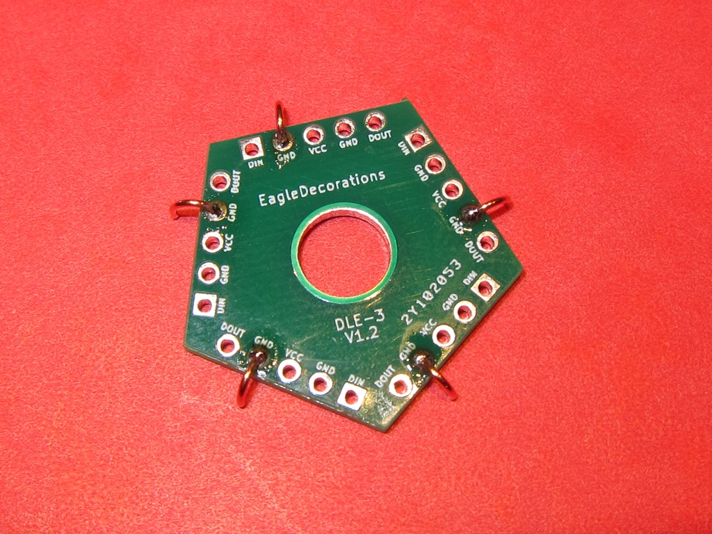
11 pentagonal faces with WS2812 (aka “neopixel”) LEDs already soldered on. There is an additional face without LEDs with a hole for mounting the DLE.
To build the kit, you will need the following tools:
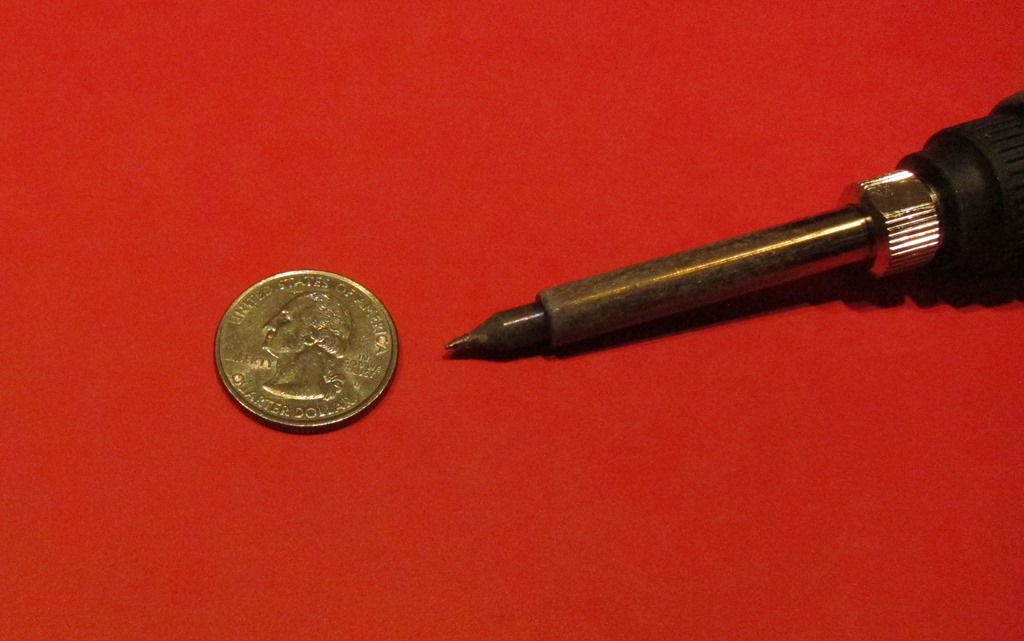
A good soldering iron with a fine tip.
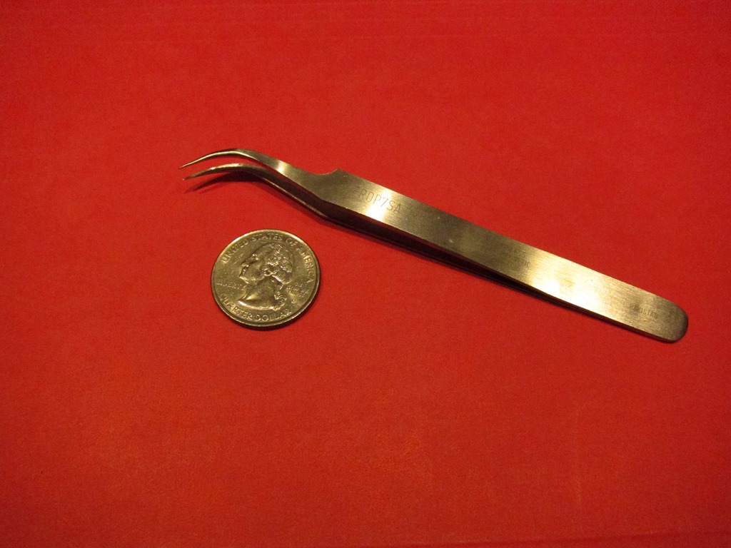
Fine tipped tweezers.
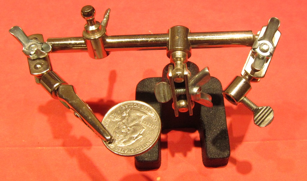
A third hand. Assembly will be very hard if you can’t hold the pieces in places while soldering.
Solder
Assembly
The globe consists of two rings composed of 5 faces each plus a top and a bottom. We will be joining together the power (VCC) and ground connections so that the LEDs all get power and ground. In addition, we will be connecting the data output from one face (DOUT) to the data input of one adjacent face so that the signals will travel correctly to all of the faces.
It will likely take a couple of hours of soldering to complete the assembly.
If you would like a refresher on how WS2812 LEDs work, there’s a good discussion on StackExchange here.
Building a ring
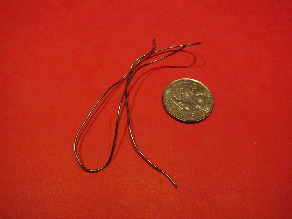
The tiny half-circle wires are very tiny and easily lost. Put them in something to keep them together. If you lose some, they are made out of 22 gauge solid copper wire.
Five of the pentagonal faces are used to build a ring.
Every face of the pentagon has identical connections so the orientation of an individual face is not important.
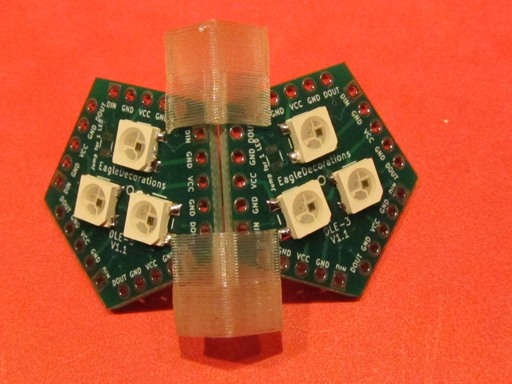
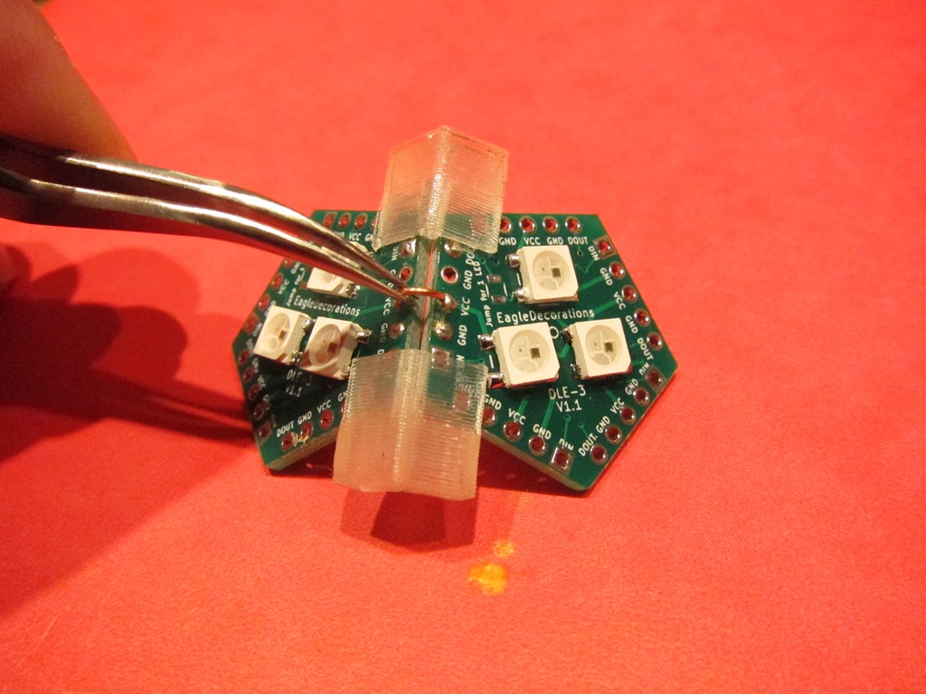
The alignment clamps are used to hold the boards together at the correct angle (116 degrees):
Note that the two boards are parallel and there is only a small space between them. Also note that the left and right boards are aligned horizontally; the two VCC holes are aligned with each other.
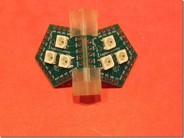
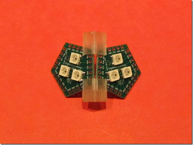
Here are two wrong ways to do it:
In the left one, the two boards are misaligned vertically; the two VCC holes are not aligned horizontally. In the right one, the boards edges are not parallel.
The board alignment doesn’t have to be perfect, but it helps to have them pretty close.
In some orientations, the alignment clamps may contact the LEDs. If this happens, don’t push that clamp on fully; it will still work if near the edge of the board:
For the faces in the ring, we will connect both VCC and GND, and then we will connect the data output from the left face (DOUT) to the data input (DIN) on the right face. We will start with VCC.
We will be using a connection wire to make the connection. I have tried a few different ways of doing this, and the following is what I recommend:
- Add solder to the hole on one side of the connection (the right side in these pictures). Add enough so that there is a ball of solder protruding above the board.
- Hold the connecting wire in the middle and place one end of the wire in the hole without solder, and hold the other end against the hole with solder in it.
- Touch the soldering iron against the end with solder and lightly press the wire into the solder. It will melt and the wire will sink into the solder. Remove the iron, and hold the wire in position until the solder solidifies.
- Solder the other end normally. It works best if you get the solder in position and only apply the soldering iron only long enough to melt the solder. If you apply it too long, you will melt the other end and may have to resolder both.
- Verify that both solder joints are shiny and have enough solder. If the joints aren’t shiny, heat one at a time until it just goes liquid.
It’s going to take a little time to get the hang of this. Don’t worry, you will get faster.
After the VCC is connected, connect one of the GNDs to one of the others. It doesn’t matter which one you choose.
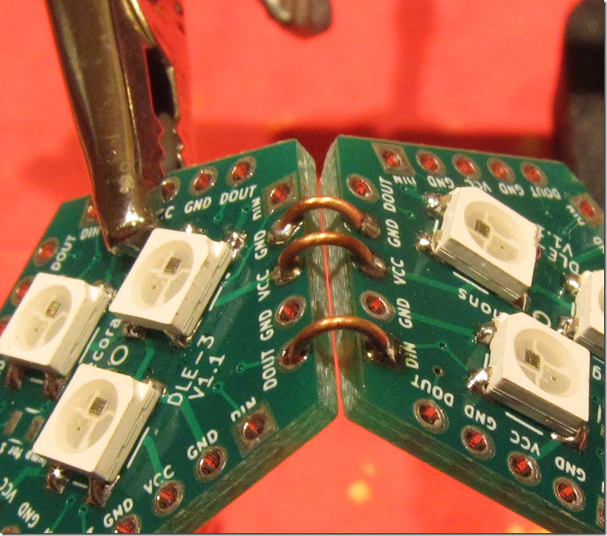
After VCC and GND are soldered, remove the assembly jigs so that you can solder DIN and DOUT. This will carry the data signal from the DOUT face into the DIN face.
In this detail, the right side (DIN) has been soldered, and left side is in the DOUT hole. The next step is to solder the DOUT end.
If the second end takes too long to solder, it may heat up the first end and the connecting wire may come loose. If that happens, just hold the wire to one end and heat it and wait for the heat to conduct down to the other end and melt the solder there.
That’s one face connected. There are a lot more, but it will get easier with practice.
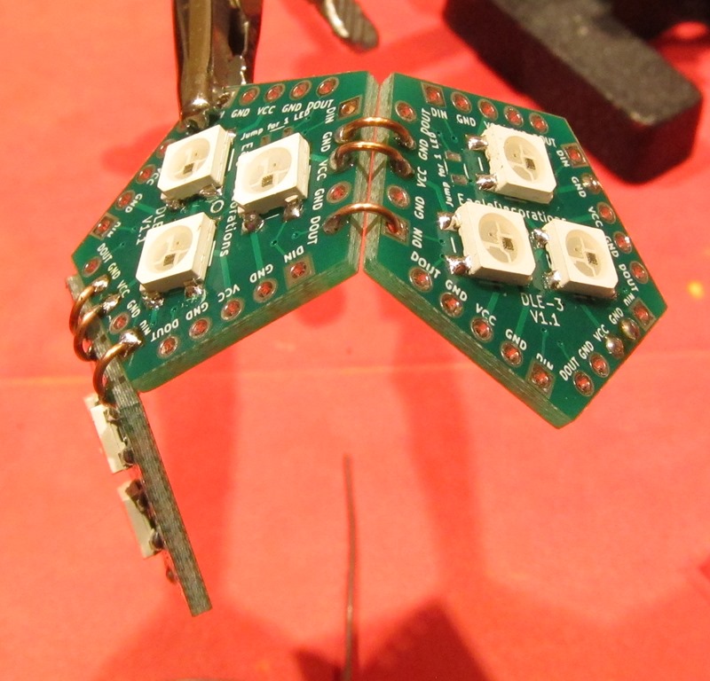
We next add a third face using the same approach. It looks like this:
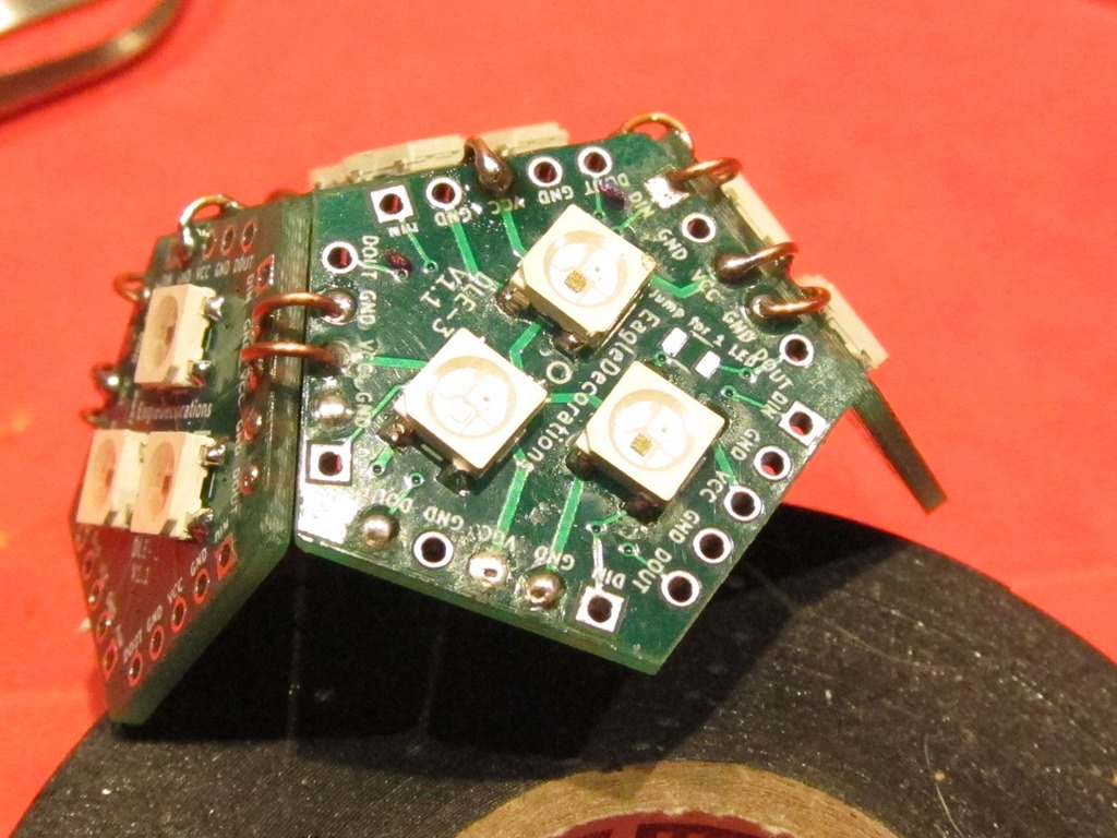
Once we have three faces, assemble two more faces together. We will assemble the three and two face pieces to make a full ring.
Make the ring
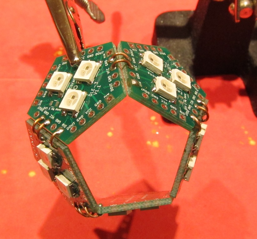
Use the alignment clamps to hook the three-face section to the two-face section, and solder one set of connections between the two section and three section.
The last set of connections is different. Note that only the GND and VCC parts are connected; the data lines are unconnected. This is so that data can come into the ring and go out of it.
Looking at the input face, we notice that there is a connection to DOUT but not to DIN; for this face, the data will come in from a face that is not on this ring and then head out the left side of the face.
Looking at the output face, we notice that there is a connection to DIN for the data that has travelled around the ring, but no connection to DOUT. The data coming into the right face will head out of the ring to another face, either the top or a ring that will be attached below.
Adding the top
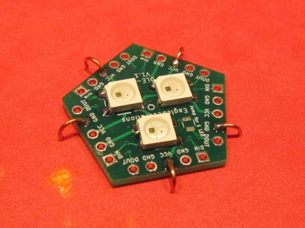
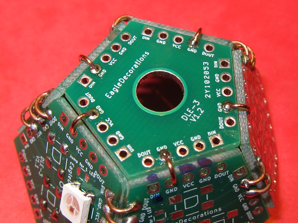
We need to add wires to the top so it doesn’t fall through the middle of the ring, and each side will connect either VCC or GND. Start by adding solder to three VCC faces and two GND faces (one arrangement is shown above, but it doesn’t have to look exactly like this).
We need to prepare one connector on each side of the board with solder; either GND or VCC. Do three faces with VCC and two with GND.
To keep the top face from falling through, we need to put connections on it ahead of time. Note that each of these touches the surface; that will give us roughly the angle we need.
The top face is just sitting there. Check that all the connections align properly with the connections from the ring. Solder all the VCC and GND connections to the ring. You may need to heat the already soldered wires to get them to align correctly with the holes on the ring.
Next, we need to make the data connection from the ring to the top. Find the face on the ring that does not have a connection to DOUT (the output face in the previous picture), and make a connection from the DOUT on that face to the DIN connection on the top face.
Finally, we find that face that has a DOUT connection but no DIN connections. This is the face that will connect across to the other ring. I have marked the two DIN connections with marker so we can find them later; ONE of these will be connected to the other ring.
If you have a controller than can drive these LEDs, it’s a good idea to test what you have built so far. Connect VCC to 5 volts, GND to ground, and DIN to your microcontroller, and run a program that can drive 33 LEDs. They should all light up. If they don’t, examine your solder connections and make sure that you don’t have DOUT/DIN connected all the way around the ring.
Building the second ring
The second ring is built using the same method as the first one. Do not add a top piece.
This is the bottom ring and is actually upside down at this point. Eventually, we will need to make power, ground, and data connections for the whole globe. They are marked in blue on this face. Why did we choose this face? It’s the only one on the ring that has a DOUT connection but no DIN connection.
It’s a good idea to test this ring at this time.
This is the output face of the second ring. I have put marks on the two DOUT connections; one of them will hook up to the input face on the other ring.
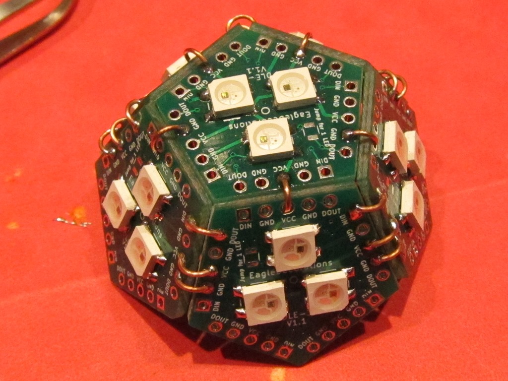
Put the first ring and the second one together, making sure to align the rings so the face that has DOUT marked on the bottom ring is aligned with the DIN that is marked on the upper ring. Tape the two rings together. Connect those two pins together, then attach the top and bottom by connect VCC between three faces and GND between the other two.
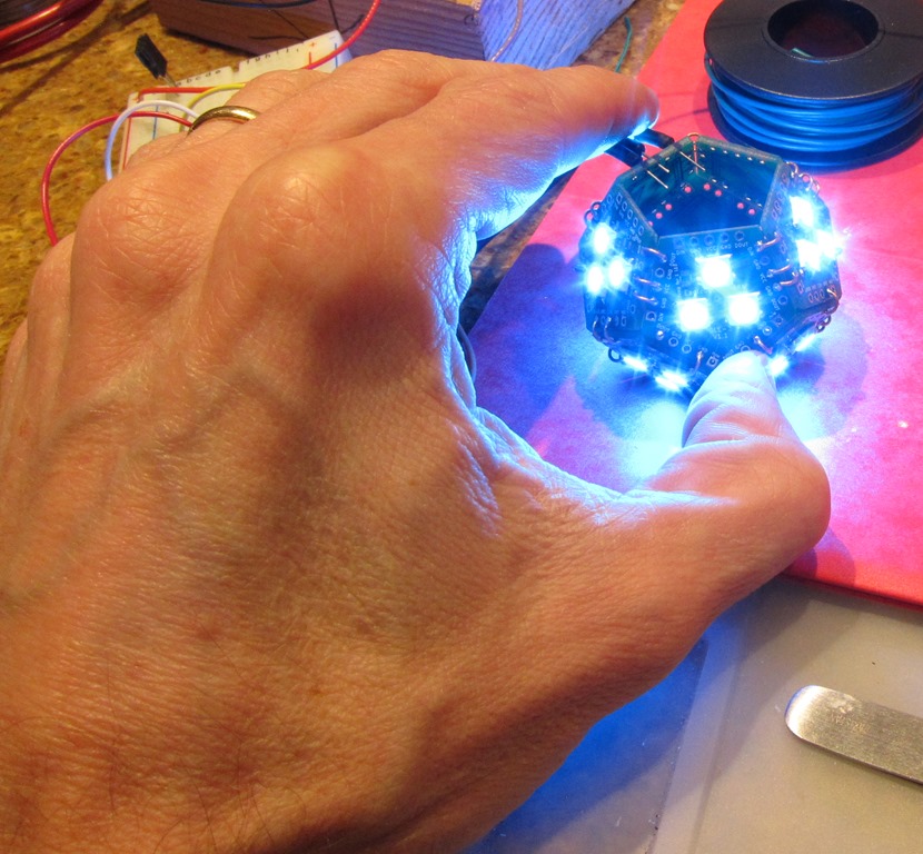
At this point, the LED part of the globe is complete. Hook it up to your controller and verify that all of the faces light up. It should look like this (hand not included):
Attaching the base
The base is purely used for mechanical support; the connections that are made do not carry electricity.
We will use the special bottom pentagon; it has a hole in the middle and no other connections. Attach 5 wires to it on the GND connections, and make sure that you use a variety of GND connections.
Find the spot on the bottom ring where you will attach the wires – you should have marked it before. Rotate the bottom until one of the grounds lines up with the gap between the grounds on the wire-attachment face, as shown in the above picture.
Do not solder the bottom on yet.
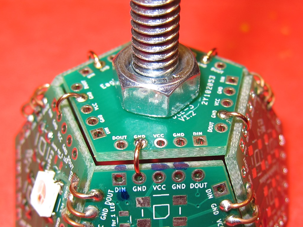
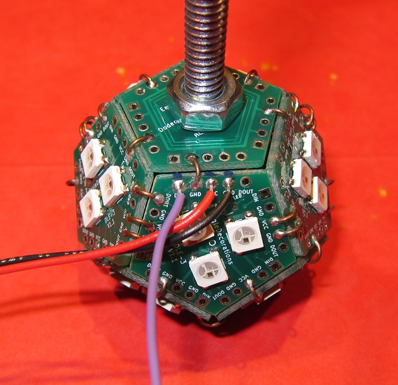
Take the 1/4 screw and put in through the bottom face from the backside, and then put a nut on the outside face. You will want to tighten this out pretty well so that it doesn’t come loose.
And then solder the wires to hold the bottom on.
Next, solder on the wires; red to VCC, black to GND, and purple to VIN.
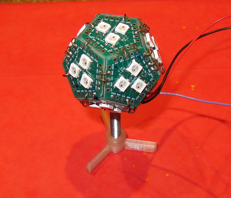
Finally, screw the base onto the 1/4 bolt, and you’re done.
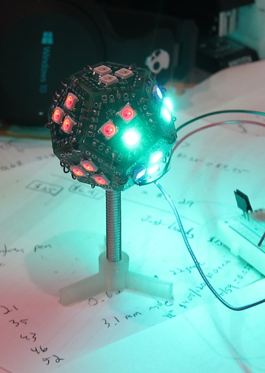
Hook it up, and it should look something like this:
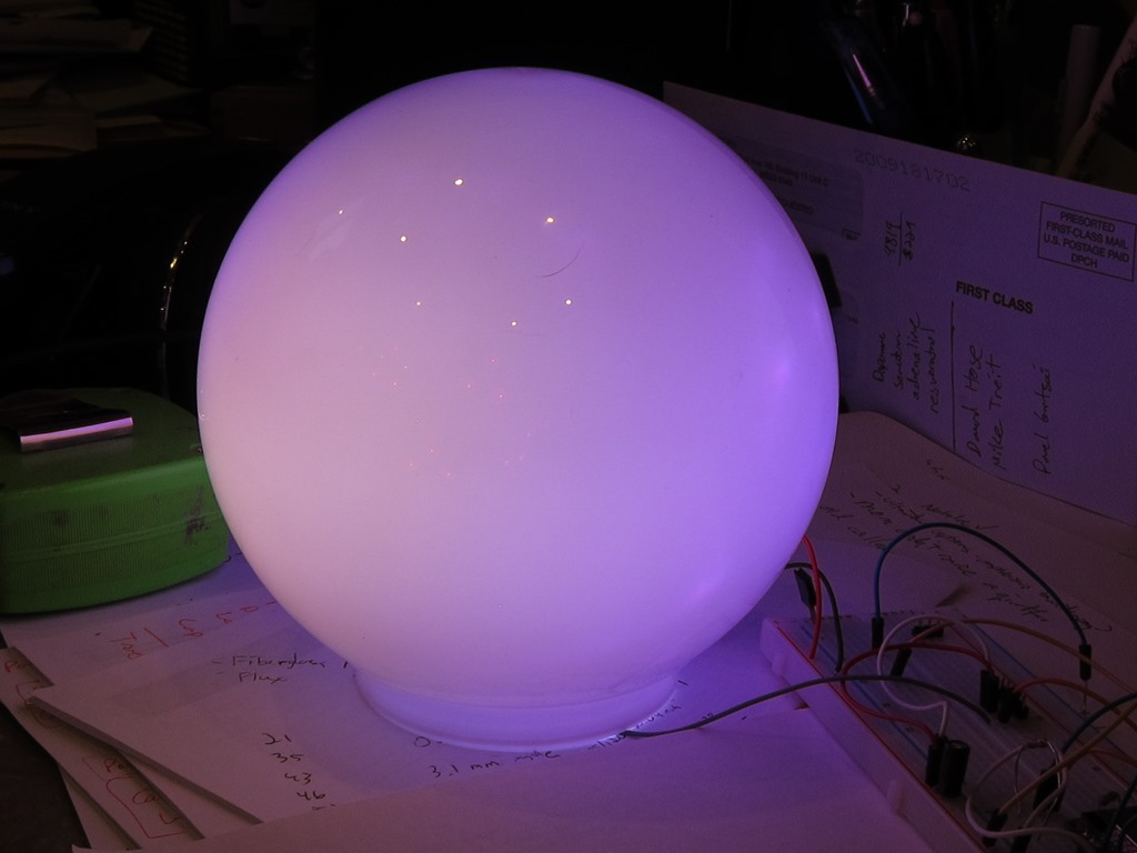
If you’d like a more diffused look, you can put an acrylic plastic globe over it
Both of these pictures are with full lights on and with the globe powered by an underpowered USB source.






So, what do you think ?