The endurance athlete’s guide to fueling and weight loss part 2.5–More on muscles and energy systems


The Dual-fuel system revisited…

In one of the earlier parts, I talked about how muscle contraction is fueled either with glucose (glycolysis) or fatty acids (beta oxidation). I have since realized that there is more detail that I’d like include, so this is a part II of that post.

The phoshagen system uses stored creatine phosphate in the cell to create the ATP that ultimately drives the muscles. This can provide a *lot* of energy, but is limited to durations of 10-15 seconds because of limited supply of creatine phosphate in the cell. This is the system that is used for explosive power – weight lifting, sprinting, etc.

The glycolytic system uses glucose to create ATP. Strictly speaking – and this is a point I glossed over earlier – glycolysis only goes from glucose (or glycogen) to pyruvate. This step can occur both in the mitochondria and in the the cytoplasm of the cell, which means it can produce quite a bit of ATP quickly, but it’s only the first step in the full process of burning glucose. To keep the energy production high, something has to be done with the pyruvate, and it is converted to lactate. That lactate accumulates quickly, and that is what is making our muscles hurt during hard efforts.

The oxidative system – also termed “oxidative phosphorylation” or “mitochondrial respiration” – is the main energy provider for aerobic exercise. As discussed earlier, there are two feeds into the TCA/citric acid cycle:

Beta oxidation takes fatty acids and converts them to Acetyl CoA to feed into the TCA cycle. Or, we take the products from glycolysis and feed them into the same cycle. The important point is that those products can be pyruvate that was just created by glycolysis, or it can be lactate that was created during glycolysis elsewhere in the cell.

That’s enough context to now discuss different intensities:

At a moderate aerobic pace, we are getting all of our energy from the oxidative system; we are either converting fatty acids to Acetyl CoA or performing glycolysis to get pyruvate which is immediately fed into the TCA cycle.

As we increase the intensity, we need more glycolysis to produce more energy, and for that to keep working, we need to convert the pyruvate to lactate. That means we have more lactate around that we will need to feed into the TCA cycle to get rid of. That can happen both in the muscle that is exercising, but also in other muscle that is resting and in the liver and heart. At some point, the amount of lactate produced exceeds the body’s ability to get rid of – or “clear” – it, and tissue and blood levels of lactate increase much faster. That is what the term “lactate threshold” means, and a lot of high intensity training is looking to improve lactate clearance.

If we increase the intensity above the lactic threshold level, we accumulate lactate very quickly, and that means we cannot continue for very long.

Here’s a cool image that shows the relative contributions of the different energy systems:

Training intensity and fat loss

Knowing that is only burned by the oxidative system tells us something important about intensity; we can only burn fat at moderate intensity. The definition of “moderate” is going to vary quite a bit based on the availability of glucose during our endurance training, but one we have hit an intensity that maxes out beta oxidation, we will not be burning any additional fat. Extra intensity above that level will just lead to more glucose being burned.

For the longer term, we could improve our ability to burn fat by improving our ability to perform beta oxidation.

Muscle Fiber Type and energy sources

image_thumb.png


Muscle fibers can be categorized in a number of different ways; you may have heard them categorized into “slow twitch” and “fast twitch”. Slow twitch (type 1) fibers are utilized in longer-term exercise, and – since they have a lot of mitochondria – they can do a lot of aerobic metabolism, and therefore can be powered on fat. Fast twitch (type 2b) fibers have few mitochondria, and run mostly on glucose. And then the type 2a fibers are hybrids, though it probably makes more sense to think of muscle fiber type as a continuum rather that a set of discrete types.

What this means for our topic is that if you are doing the sorts of activities that recruit a lot of fast-twitch fibers, that’s going to require a lot of glucose. And therefore, you won’t burn a much fat from those sorts of activities, nor will you be able to do those activities well if you are very limited in glucose.


Part 3: Carbohydrate and Fat use in actual athletes…


References

Interaction among Skeletal Muscle Metabolic Energy Systems during Intense Exercise


Skiing penguins build log retrospective

My skiing penguins project has been up and animating for a few weeks, and I thought I’d write down the process for others so that they can learn from what I did. And also so I can remember what I did and why. There are some other blog posts that talk about some of the specifics for the sequence controller I built.

First off, there’s a video here that shows the final result.

The my initial idea was to do something with LEDs and single frame animation; see some of the animations that were done at ZooLights at Pt. Defiance many years ago was what got me into this hobby. I had a big garage roof that was unutilized, and after some discussion with my wife we decided that skiing penguins was a good place to start.

CAD

 I started looking around for online penguin designs to use as a starting point and found a couple. Then I started up Fusion 360 and created a new project.

I design (and sell) LED ornament kits, so I’m used to doing these designs. Here’s a video that shows the technique that I use to space the LEDs out evenly along an outline; that is what I used for all of the penguins. Here’s a in-process look at one of the designs:

image

and a final one:

image

The final designs were too big to cut in my laser cutter (glowforge), so I had to break them into two pieces. The puzzle-piece line gives me two individual pieces to cut that can easily be put together again.

The animation has 15 frames, which meant 29 individual pieces to cut.

Cutting

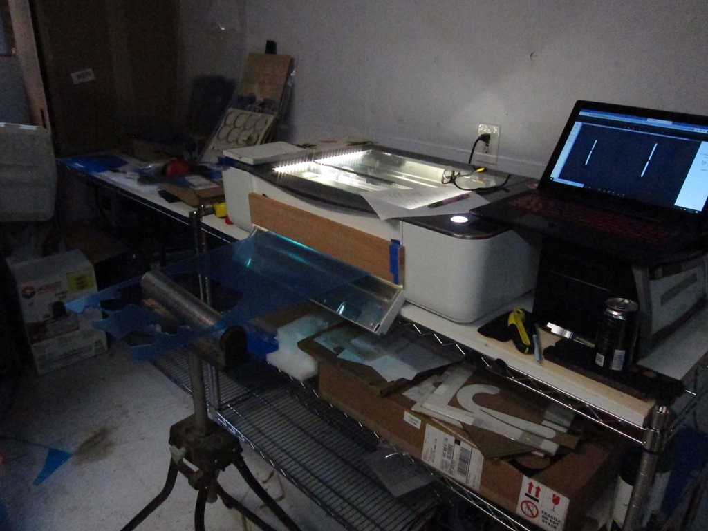
I figured out what sizes of plexiglass I needed and bought the plexiglass from my local TAP plastics; it was about $90 worth. I didn’t want to spend a lot of time splitting pieces on my table saw, so I defeated the door interlock on my Glowforge for the larger pieces:

IMG_9644

You really shouldn’t do this if you don’t have laser safety glasses designed for your particular laser’s frequency. In this case, I wore my normal safety glasses and closed off as much of the opening as possible; I now have a nice set of dedicated laser safety glasses. Don’t do this unless you understand the risks.

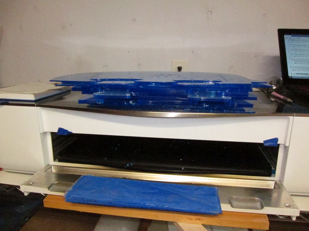
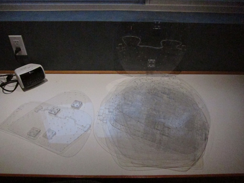
Here’s all the cut pieces stacked up:

IMG_9647

This is a penguin prototype:

IMG_9651

This was actually constructed earlier; it was used to determine size, and we decided to go about 25% larger. Thankfully, Fusion made this fairly easy to do.

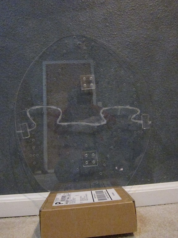
Here’s the first production frame:

IMG_9654

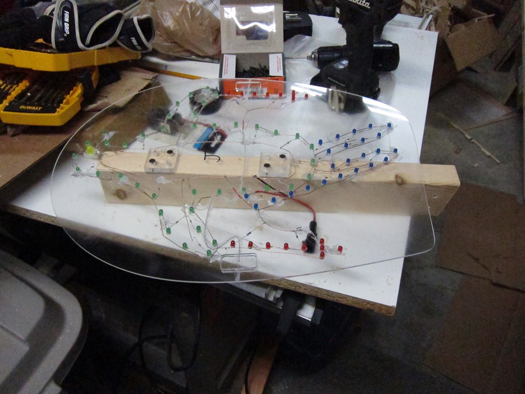
You can see the glue residue along the joining line. At the left and right sides there are short connectors that overlap the joint and provide much needed stiffening; they are on both sides. The squares with holes are spacers; the penguins will mount to wood supports and the spacers hold the wood away from the wiring that will be on the back. Zoom in to see the fine details.

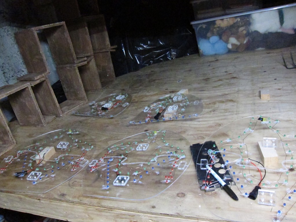
Here’s the pile of penguins all glued together and ready for LEDs.

IMG_9656

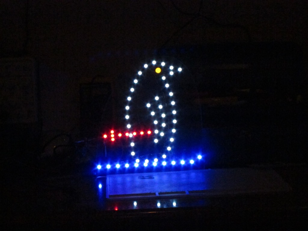
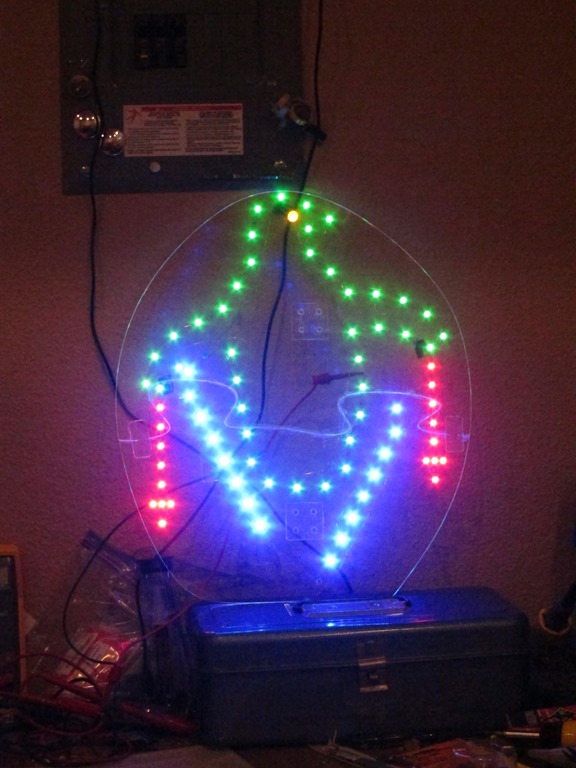
First light on the first frame:

IMG_9659

Green was planned for the body outline rather than the white in the prototype but I didn’t have enough green LEDs at the time. The LEDs are brightness matched to look similar to human eyesight though the blues look too bright to the camera. Only 13 more to go!

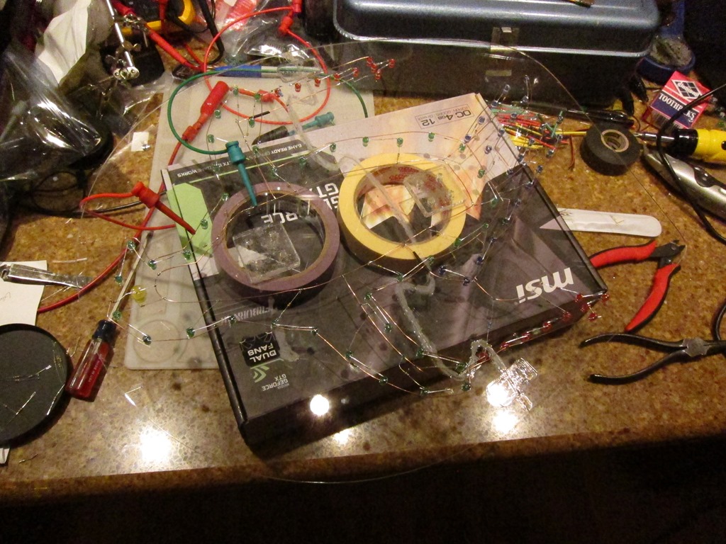
Here’s what the penguin looks like with the leds off:

IMG_9660

Sorry about the messy and distracting background. For each section of LEDs, there are two sets of bare copper; one that is connected to 12V and one that is connected to ground. Leds are grouped based on their voltages; green and blue run in groups of 2 while reds run in groups of 4. At this point I realized that my ski poles had 9 leds which means that I had two groups of 4 and one individual LED, which was a pain. Each group has the appropriate resistor to set brightness. There are 70-odd LEDs in this frame, so figure something near to 200 solder joints.

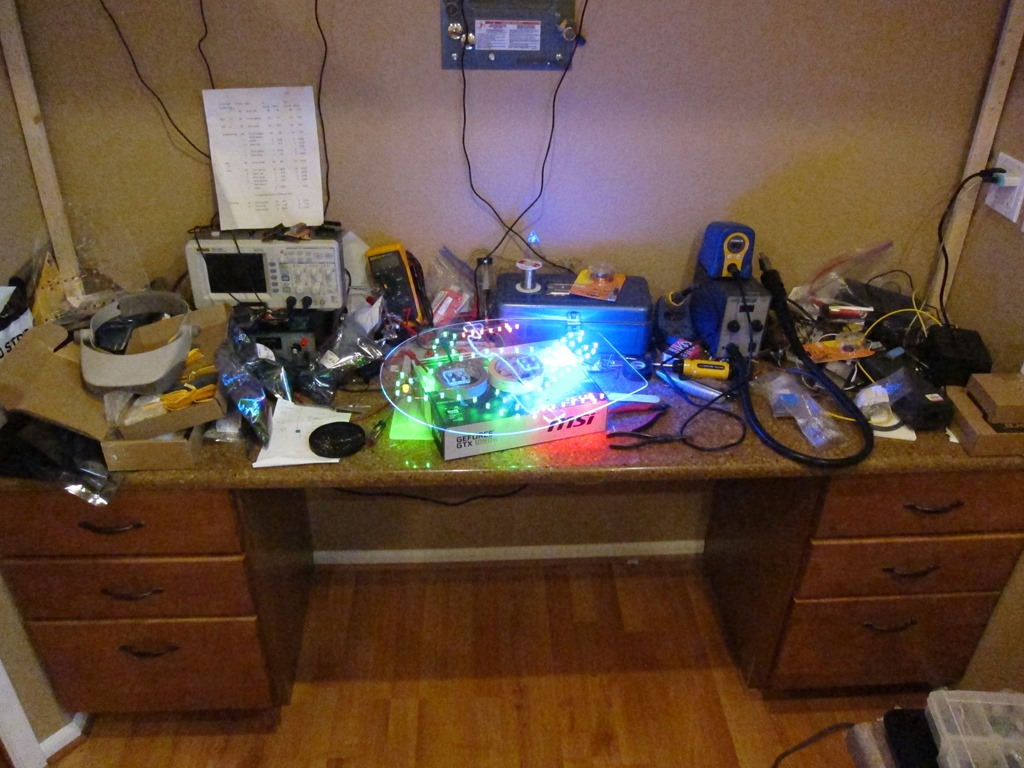
Here’s a picture of the workbench mess:

IMG_9662

That’s not that bad except there is more mess here:

IMG_9663

and here:

IMG_9664

To waterproof all the wiring, I took the penguins outside and hit them very heavily with clear acrylic spray. I’ll know how well that worked when I take them down:

IMG_9665

Here’s a view of them drying. They have waterproof power connectors attached and have frame numbers marked on them.

And then they were each mounted on short pieces of 2×3 wood which would have been painted if I had time; maybe I’ll do that when I pull them down after they have dried out. You can see the wiring quite well in this shot, and we can see that it’s frame “J”, or the 10th frame.

IMG_9670

The next step was to build the wiring harness. I did a diagram of the expected layout in Visio:

image

From that, I went out into my driveway, took a couple of tape measures, and laid out what I needed. The controller was planned to be under the roof where “K” is, so I would run wire to that point and then leave an extra 10’. I unfortunately don’t have any pictures of this process; I was racing the weather.

Basically, I would start at “A” in the diagram, leave a couple of feet of slack cable, run it up to D, across the top, and then down to K and leave 10’ at that end. Each cable gets an adhesive label with the circuit letter at each end, and those will later be covered with clear packing tape to waterproof them. Continue the process with each cable all the way through K. The cable is 22-gauge alarm cable; I have used twinlead in the past and I have to say that this cable was a huge upgrade in terms of ease of use, and at $31 for 500’ is was pretty cheap. I did calculations on the voltage drop and decided that it wasn’t too bad (about 7% IIRC).

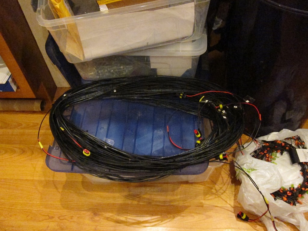
Once I had all the cables, they got bunded together with wire ties at every branching location and then additional wire ties to make the harness easy to handle. I got it all done just as the rain came down for real, and headed inside. Each penguin location got the other half of the waterproof connector soldered on and then covered in heatshrink tubuing, and the controller ends got stripped to be connected to the controller. Here’s the final roof harness:

 IMG_9671

The penguins got installed on the roof with various arrangements of wood to support them and were plugged into the harness. I then spent a day or two figuring out how to do the penguins in front of the house; they are supported on 1/2” metal EMT tubing. I also created a separate harness for those penguins (one in the air, one crashed in the tree, and then a small one where the one in the tree lost his poles and skis) using the same process.

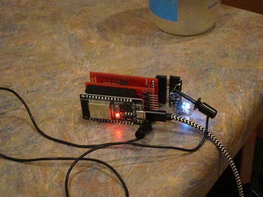
I finished building the controller:

IMG_9672

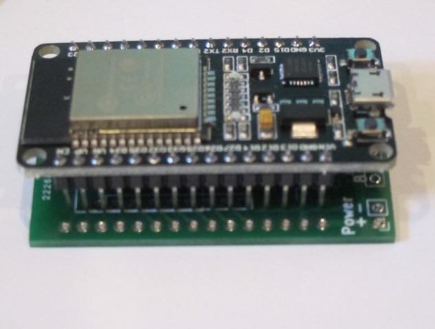
Nearest to us is the ESP32 controller board that runs the animation software, and behind it are two custom 8-channel MOSFET switching boards. Attached to the back MOSFET board is a series of LEDs used for debugging.

The ESP runs custom software that drives the ESP32’s 16-channel PWM hardware. The ESP32 is ridiculously full-featured for the price. One of my goals for the project was to *not* have to pull the controllers out of their installed location to update the animation, so I created a really rudimentary web-based IDE and an animation language:

image

This is the current active view from the ESP running the penguins as I sit here and write. The left textbox shows the code and the right one shows errors if there are any. I wrote the animation outline and programmed it in, and then took my laptop to the garage and we’d watch the animation and I’d tweak it as necessary, it took us about 10 minutes to get what we wanted, and I would have spent more than that on a single iteration of “unplug the controller, take it downstairs, plug it in, modify the software, compile it, upload a new version, take it outside, plug it back in, and see if it worked”. That worked very well.

I’m calling the language “Dim”, because it’s good at dimming things and not very smart. In the code “DI” means drive a specific channel to a specific brightness over a specific cycle count (each cycle is about 10mS, so it runs at 100 Hz), and D lets you specify more than one operation to occur at once during the following “A” (animate) command. The language does have for loops but is desperately in need of functions/methods for this usage; I have those in a newer version.

Here’s a bit of code running on a second instance of the controller that flashes 5 of the ornaments I make in a random pattern:

channel=2
FOR count 1:100
   D(50, channel, 0)
   channel=R(1:6)
   DI(30, channel, 1)
ENDFOR  
      

That took about 5 minutes to write.

Finally, here’s a daytime tour of the installation which shows the penguins mounted on the roof and in front of the garage and the controller board with terminal strips.


WPC opto issues…

I’ve had an ongoing issue with my World Cup Soccer ‘94 – at certain times in the game, it will push balls into the plunger lane when it shouldn’t. That points to some sort of problem with the sensing of the balls in the trough at the bottom of the game.

WCS is a WPC – I think that means “William Pinball Controller – and one of the nice features of the software that runs the game is that it has some test software that lets you visualize the state of the switches in the machine:

In my testing, the trough switches work fine when there is a ball in them, but if there is no ball in them, they cycle between open and closed. That is likely to be the problem. I verified that the trough LEDs and opto are functioning correctly and I’ve done the usual “unplug and replug all the cables” approach, so it’s time to dig further.

I did a post on pinside – which yielded no responses – and then pulled out the 7-channel opto board. It looked fine, but when I put a VOM on it, I found 10 VDC and 2.7 VAC. Not good.

I should mention that this machine had some issues on the power driver board, so I took an opportunity to recap it, so I knew that my supply voltage was fine. which meant the most obvious culprit was the 100 uF cap on the opto board.

Except it wasn’t; replacing that caused no real improvement. Which led me back to the power driver board where I found similar voltages at the test point. I pulled the board, found no continuity between the – terminal on C30 and ground, which meant I damaged the through-hold plating with my recap and it just took a while to fail. I added a jumper between the cap terminal and the adjacent ground trace – it would have been trivial to add a trace there, but for some reason they didn’t.

Put the board back in the game, everything works fine. Later I found a note in the WCS repair guide that said, “if the optos are malfunctioning, it’s usually a connection on C30”. Yep.


A self-expanding ESP32 PWM board…

I’ve been working on a little ESP32 expansion board/shield for an LED project I’ve been working on. One of the nice things about the ESP32 is that it has a peripheral known as “LED control” that provides 16 independent channels of PWM for controlling LED brightness, and my project uses that capability.

One of my projects is going to require all 16 channels, so I wanted to do a board that would support 16 channels, but I also wanted a version of the board that would only support 8 channels. I started with the 8 channel board and figured out a way to build a single board that would support 8 channels and also function as an expansion board to add the other 8 channels. I thought the approach was interesting enough to share it here…

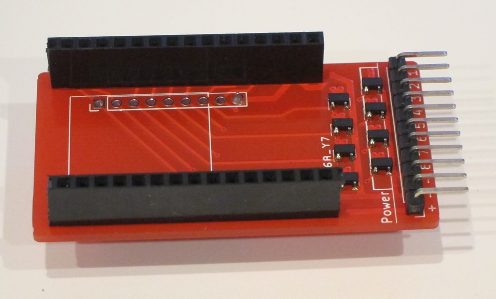
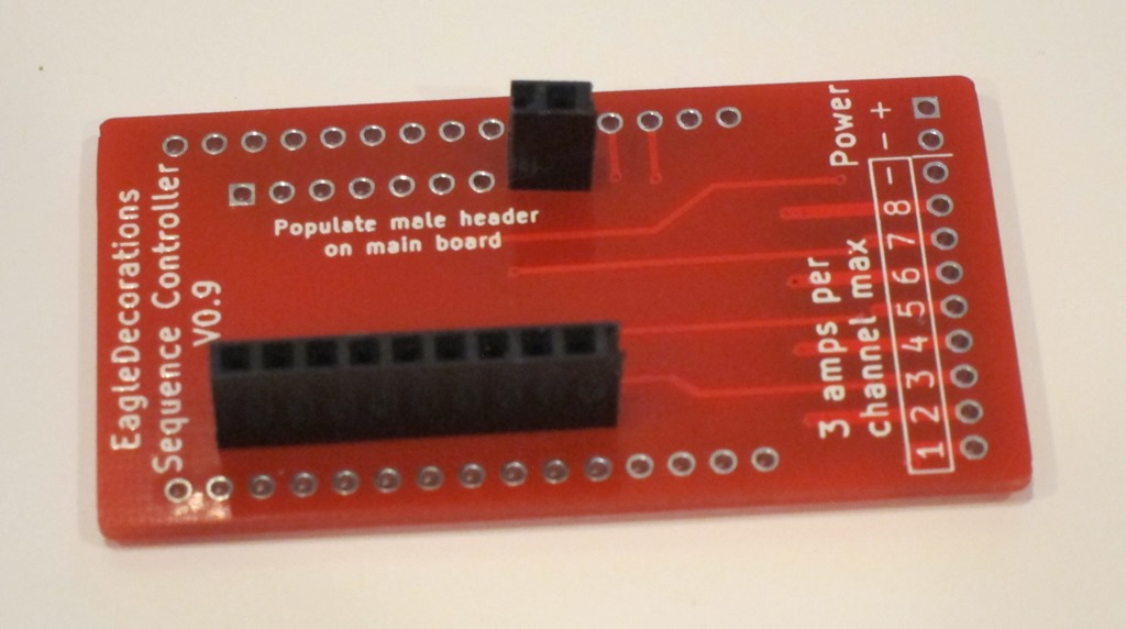
Let’s start with a picture of the board:

image

I’m using the 20-pin development board, and it turns out that of the 16 channels supported by the LED control peripheral, half of them are on each set of pins. I started doing an 8-channel version of the controller; you can see the primary pins on the right side of the board that come into the center of the board and then head down into the MOSFET region of the board. That design was fairly simple to do.

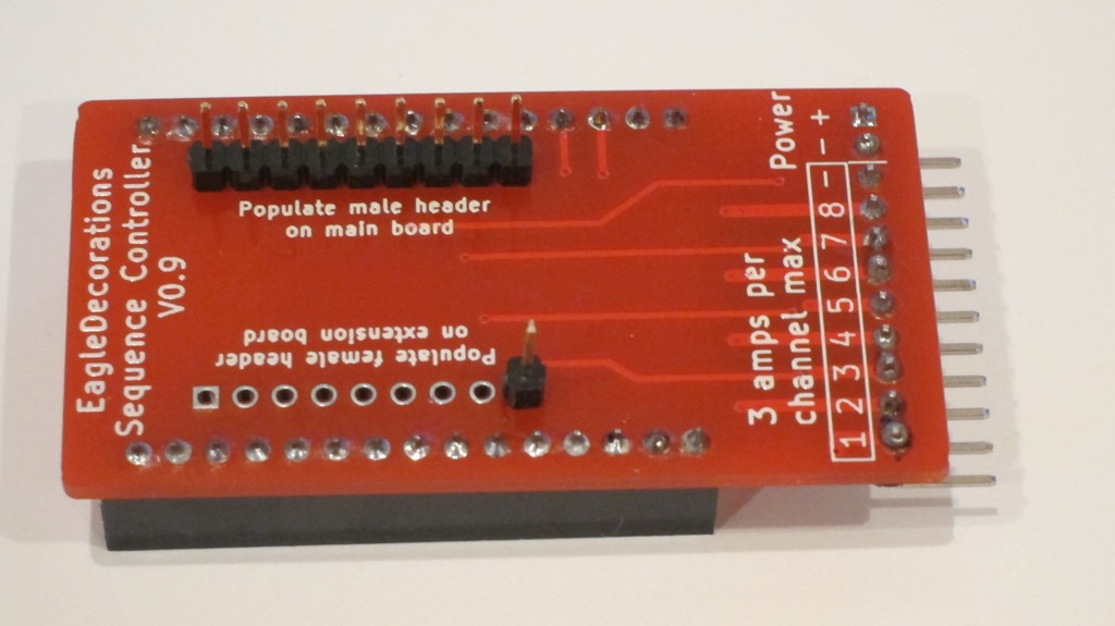
Then I needed a way to do something with the 8 channels on the other set of pins. At that point, I realized that if I could use the same board to get the other 8 channels if I flipped the board over:

image

On the primary board, the pins for channels 9-16 on the left side of the board are connected to a header. The ESP32 will be connected to headers on the top side of the primary board, and then we will add a header to the primary board expansion pins – pins 9-16 – on the underside of the primary board.

We will then take a second board and flip it upside down. That puts the header pins that are connected to the MOSFETs on the left side of layout directly under the header on the primary board connected to the expansion pins, so we can just put a complementary header on the expansion board and just stack them together.

Here’s what it looks like in the real world. This is the primary board with headers for the ESP-32 on the left and MOSFETs on the right. That is set up for 8-channel mode.IMG_9631

To enable 16-channel mode, we flip this board over and add some headers. The top header connects to pins 9-16 from the ESP32, and then there’s a single pin on the bottom which connects to ground (if I do a future version I’ll add an extra pin on the left) to provide a bit more support.
IMG_9632

We then take a second board and set it up as an expansion board by adding the complementary headers to it.

IMG_9633

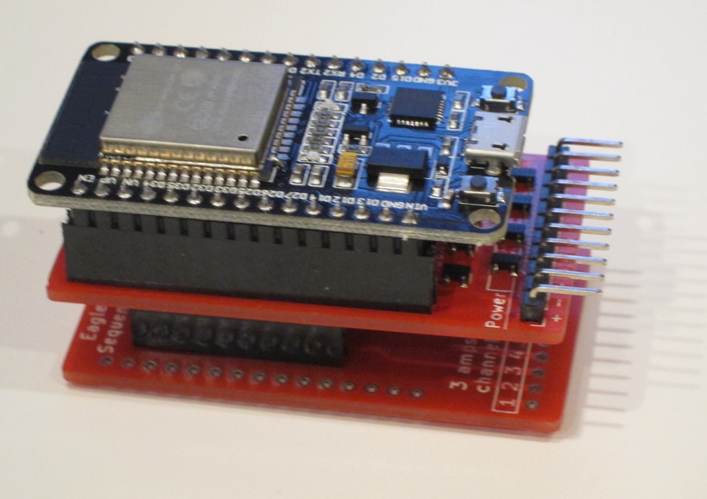
We can then finally stack the expansion board on the back of the primary board and add the ESP32:

IMG_9634

That gives us 16 outputs.

Here’s a short video demo of the controller:

And a second video that show my first project using it:


Happy Zoo Year…

Image result for cougar mountain zoo sign

Traditionally, winter has been the off-season for me. It gets rainy so only about half of the Tuesday/Thursday night rides I schedule actually occur, and we’re skiing on the weekends, so I go from 3 rides a week during the season to 1 ride a week, on average. My fitness slowly decreases and, come March, it takes a lot of effort to get it back.

Last fall I realized – I can be a bit slow at times – that since I was now retired, I had the chance to keep a bit more of my fitness by riding more during the winter on weekdays. And perhaps I could keep my climbing legs as well.

I also realized – well, already knew – that my well-known laziness would be the biggest issue, so I needed a more defined goal. So….

12 Months of Zoo

Was born.

The rules are pretty simple:

The first trip was the Sunday of Thanksgiving week,  November 18th at 1:48PM. The climb took me 34:19, which is pretty much average for me. I also climbed the backside of Summit which is sortof on the way back home and features one of my favorite descents to the north.

December weather is always really hit and miss and we are generally skiing the whole month, but the snow was late so I did a quick ride on Saturday, December 15th in the early morning. 35:52. I added in Pinnacles at the top and a really painful climb off of 164th on the way back.

January, the weather, skiing, and seasonal ennui conspired against me, and it wasn’t until 11:02 AM on January 28th that I made the “JanuZoo” ride, completing it in 35:34.

February 2019 was the snowiest month in Seattle in 50 years. Snowy at my house at 300’ means a lot more snowy at 1300’. Eastside Tours rode a total of zero times for the month, the first shutout I can remember in the 15 years that I’ve been on the ride. It froze overnight and then barely got warm enough during the day.

But between storms on February 21st at 1:01PM, I bundled up and headed out into the mid-40s weather, heartened by the a bit of sun. West Lake Sammamish was cold but not icy, at least none that I saw. I hit Newport and started the climb, with remnants of the last storm still piled up to the side of the road. The road was dry-ish, however, so I kept climbing. Pretty much none of the climb had seen any sun and it all had snow on the side, which pushed the temp down into the mid 30s, but it really wasn’t that bad as I climbed at a lackluster 167 watts. I finished the middle part, and turned onto the top – which sees less traffic – and the snow got higher. A few minutes later, I reached the false summit, descended, and got ready for that last little push to the top.

The road was plowed because there’s a reservoir and antennas up there, but not really very well – there were some clear tracks that were not dry and some snow/ice on the road, and 16-18” on the sides. Hmm. 18-20%, check. Air temp just above freezing, check. Areas of dubious traction, check. And I decided that I wasn’t willing to risk the rest of my ski season and the spring biking season just to ride up a short piece of road. So, I got of my bike and hiked up the damn thing, pushing my bike along with me, for the couple of minutes it took to walk to the top and a 36:41 completion time. And the road was fine, at the top, I clipped back in and slowly and carefully rode down, and quickly found out the real problem. Even unzipping, I get sweaty on the climb and the descents are a field experiment in wind-chill factors. The rest of the ride was the minimal one, just to get home.

With all the issues in February, I decided to hit March early, and on March 13th I headed out at noon and rode both Squak Mountain and Zoo. My ancient Garmin Edge 705 crapped out the week before, so I have no riding data to support this ascent, though I will note that there was about 15” of snow at the top of Squak and I have evidentiary pictures of the top of the Zoo. This is mostly the leftovers from the February storms.

ZooUpZooTop


April 7th brought “A Grand Squaky Zoo”, climbing 3 of the 4 big climbs from Sufferin’ Summits – though not the hardest climbs. The Zoo climb was done in 36:03 and 179 watts on my new Garmin 520 Plus (or is that “+”?).

Sunday, May 5th was Day 1 of minicamp where I rode 5 days straight in a quest to jump-start my fitness. It featured Squak, the extremely painful Telus North climb up James Bush Road, and Zoo in 35:21 at 184 watts.

Sunday, June 9th brought the “3 Biggies” – up Grand Ridge, Squak, and Zoo again. Zoo was dispatched at 32:25 at 208 watts, a nice improvement. And June 29th brought “The Reservoir Rendezvous”, with Grand Ridge, Squak, Telus, Zoo, and Summit. It also brought my slowest trip up at 39:55 and 183 watts, because I was chatting with Douglas Migden from Freemont who is training for the Transcontinental race in Europe doing Zoo. He does Pinnacles at the top rather than the classic top, which doesn’t meet my strict definition of a Zoo climb, but I decided to cut him some slack because he was doing it 6 times that day, plus riding from Freemont and back. My slowness was also attributed to a bout of kidney stones on the 19th, which knocked back my training for a 10 days or so.

Two climbs in June made July pretty obvious, with three climbs as the goal. I did them all in one day in the ZooZooZooSummit ride on July 20th. 38:32 @ 169 watts, 37:30 @ 171 watts, and 34:15 at 191 watts. Disappointingly slower than my early June climb, despite having a group to rabbit after on the third trip up. But 5100’ in 36 miles is pretty good.

There’s something a little embarrassing at this point. I did the triple on the assumption that I had started the year of Zoo in August of 2018 to put an emphatic completion on the year. Then I went back and looked at my data and realized that while I had done serious climbing in both September and October, there were no zoo climbs. Sigh.

August 17th was Sufferin’ Summits 2019. I had managed to squeeze in an abscessed tooth in early August for another week off the bike, and then I pulled a hammie playing soccer on the 11th. My zoo climb was 33:16 @ 193 watts, which was somewhat surprisingly my second fastest ascent of the year despite my time off and my goal to ride slowly on this ride. Hill #5 – which includes “the widowmaker” – was the last one I completed on Sufferin’ Summits (not for the first time).

September 7 brought a “Minimal Zoo”, with 20.3 miles and the flattest route up the zoo and back home. 35:03 @ 180 watts and not feeling very good at all despite starting in the afternoon.

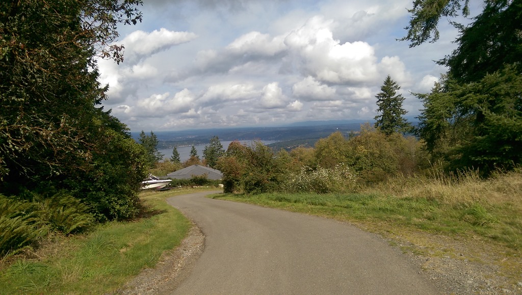
October found me seriously – rabidly even – uninterested with the project, but I pulled on riding clothes for what might be the last jersey/shorts climbing day of the year and headed out. I finished with a thoroughly demotivated – and demotivating – 37:47 @ 169 watts, but finish I did, capping off 15 ascents in the period of 12 months. Here’s a picture facing north. The lake is Lake Sammamish, and off in the distance you could see the Olympics and Mt. Baker if they were available to be seen.

IMAG0417

And thereby completes the cycle of the seasons and the year of the zoo…


Sequence Controller Part 3–Board design and MOSFET testing…

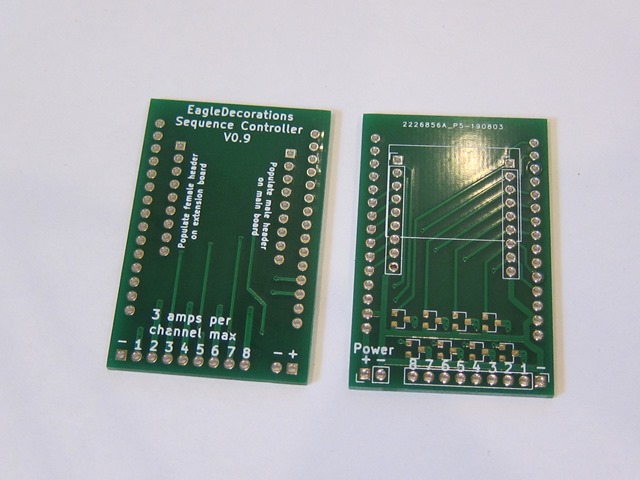
Boards are in the house!

IMG_9608

JLCPCB did a nice job, and the boards look fine. Except:

IMG_9609

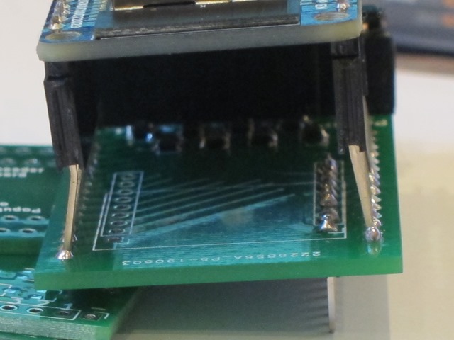
Yeah. Those pins are beautifully aligned a very precise 0.1” from where they are supposed to be…

Pro tip: Print out your design and put your components on it so that you can check the design.

Meta pro tip: Follow your pro tips.

Anyway, that’s not the only problem; it turns out that the power and LED parts of the connector are right underneath the end of the board, so you can’t use a normal header on them (you could use a right-angle one if you wanted), so I did a new revision of the board with 1.0” rather than 1.1” for the ESP and extended the board so the connectors are out on the end. That’s on the slow ship from China right now.

Then I did a bit of bodging with some long-tail female headers so I could still do testing.

IMG_9611

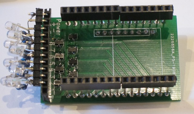
Then I put a header for the LEDs and carefully soldered 8 resistors and LEDs to the output pins, so that I have an 8-channel version available for writing software.

IMG_9612

The MOSFETs are pretty darn small, but soldering them was mostly okay. I didn’t bother doing a stencil for this rev so I could reflow, but I will likely do that for the next version.

I have not yet tested what I think is the coolest part of the design; the board is both a main board and an expander board; you can connected a second version of the board on the back of the one with the ESP32 connected to it, and it will get you channels 9-16.

Here’s a quick video of the current state:


Sequence controller test from Eric Gunnerson on Vimeo.

It’s doing a “breathe” on all 8 LEDs with varying timespans for the delay action.

This is the 6th or 7th time that I’ve written sequencing software; there was a Motorola HC11 version, two AVR versions with AC dimming, a 4-channel chaser, and a couple of WS2812 versions.

They were all very simple; take the current state of all the output and drive the outputs to a new state over a given period of time. That works fine, but writing the animation can be annoying and it’s not very compact. This time I wanted to do something different and more elegant:

Here’s my spec:

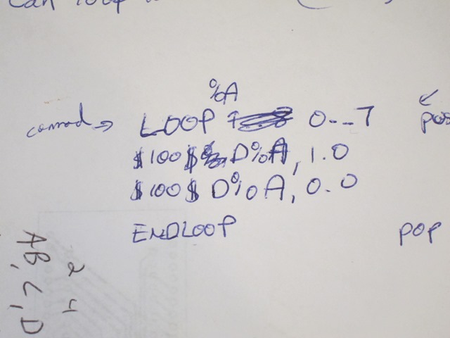
     IMG_9614

That means ‘loop variable %A from 0 to 7’, and then execute a 100 cycle (1 second) dim of channel %A from its current state to 1.0 (full bright), and then do the same dim back down to zero.

I also wanted to write the vast majority of the code on my desktop, so I took a break and wrote three blog posts about how I do that. It’s basically compile-time dependency replacement with unit tests mostly written using TDD.

Then it was off to writing a *lot* of test code and a lot of classes; 18 difference source files, only two of which are ESP specific at this point. And 15 test classes to drive the tests. It mostly worked great, I did 95% of my coding and only had once latent bug that I had to track down on the ESP32. It was weird one that turned out to have very random behavior. I suspected it was uninitialized data, and that turned out to be mostly right; two subsequent calls to a method used the same stack and I forgot that strncpy doesn’t copy a null. But it all works now. Here’s the code the video is running:

$1$LOOP %B 100:10:-10
    $1$LOOP %A 0:7
        $%B$D%A,1.0
        $%B$D%A,0.0
    $1$ENDLOOP
$1$ENDLOOP”

Variable %B is used to change the cycle count for the operations from 100 to 10 in steps of 10, and then the inner loop cycles through the 8 different outputs. Everything works great.

The code all lives here if you want to see the actual code or a more realistic testing example.

Next steps:

  1. Wireless implementation to do the connection to the ESP
  2. Save and load of the animation
  3. Web interface to edit the animation.
  4. Change the language to move the cycle count into the “dim” command, as it’s not necessary for the loop commands.
  5. Build a second board to test channels 9-16.


Just enough biochemistry – Insulin resistance and Gluconeogenesis

Disclaimer: “Just enough biochemistry” means I’m going to be simplifying what is some very complex biochemistry. Sometimes the omitted details are going to matter.

****

There’s this weird thing that happens as part of insulin resistance that I don’t think gets discussed often enough, and since I think it drives much of what is bad about insulin resistance, I’m going to discuss it here. We’ll start with glucose metabolism:

Elevated blood glucose / elevated insulin

When blood glucose is elevated, the pancreas secretes insulin, and that changes how the body’s metabolism operates:

image

Insulin is a signal to pull excess glucose out of the blood. The body has 4 ways to do this, shown as purple arrows in the diagram. The are, from the right to the left:

  1. Store it as muscle glycogen. There are a lot of muscle cells in the body and the conversion to glycogen is quick, so they can take up a lot of glucose quickly – that is is why the arrow is so big. But their ability to take up glucose is dependent on how much glycogen they already are storing – how much space there is for new glycogen. There be a lot of extra space after a long run and very little space after a few hours watching TV.
  2. Store it as liver glycogen. The liver can’t store quite as much glycogen, but it can still store it pretty quickly.
  3. Burn it as it comes into the bloodstream. The size of this arrow depends on what you are doing; if you are just sitting it’s pretty small, if you are exercising it can be bigger. With high insulin the body will choose to burn more glucose and less fat; notice the small size of the fat arrow.
  4. Convert it to fat. Excess glucose that can’t be handled in the other ways will be converted to fat and stored through a process known as “de novo lipogenesis” (“new fat creation”). The body isn’t very fast at doing this, so this arrow is small. If there is a lot of glucose to convert to fat, this process will take hours.

Broadly speaking, this part of the diagram is about storing glucose energy that is coming in from the diet.

Low blood glucose / low insulin

When blood glucose is low, the pancreas secretes glucagon:

image

When the blood glucose is low, the glucagon is a signal to do something to increase the glucose in the blood.

There are only two sources – outside of eating – to raise blood glucose when it is low:

  1. The glycogen that was stored in the liver previously can be converted back to glucose and released into the bloodstream. This is good for the short term, on the order of a few hours, but at some point the liver will run out of glycogen.
  2. If glycogen stores run low, then the body will convert metabolic leftovers into glucose through a process known as “gluconeogenesis” (new glucose creation). This might be temporary until more carbs are eaten, or it might be continuous if there is little glucose coming through food.

When glucose is rare, the body will try to conserve it, so it will burn proportionally more at; that is why the fat arrow is bigger in this part of the diagram.

There is another process – ketosis – that kicks in when there is little glucose coming in from the diet, but that’s a bit beyond the scope of this discussion.

This part of the picture is about running the body on energy that has been previously stored.

The full picture

Here’s the full picture:

image

This diagram shows how a healthy – insulin sensitive – metabolism works. If you eat a meal that has enough carbs to raise your blood glucose, you will be in the top half of the diagram. Between meals – and especially at night – you will be on the bottom portion of the diagram.

Blood glucose and insulin resistance

One of the tests for insulin resistance/type II diabetes is the Oral Glucose Tolerance Test. In the OGTT a person who has fasted overnight drinks a solution with 50 grams of glucose in it and their glucose level is measured every 30 minutes.

image

This chart shows data from an OGTT for three different people.

Because these people have fasted overnight, we would expect them to have used liver glycogen to keep their blood glucose up for most of the night, and that would leave them with some room to store most of the glucose from the test. If that were true, the glucose could be stored quickly without a lot of blood glucose change and a couple of hours later things would be back to normal. And that is what we see on the “normal chart”.

The discussion about the other lines would typically focus on how much higher the blood glucose levels are and how much longer they take to get back to the starting point, but I want to focus on another factor. Note that the other lines start at significantly elevated blood glucose levels. I find this puzzling; let me explain why…

Looking at the patient with moderate type II diabetes, we see that in a span of 90 minutes, they got rid of a lot of blood glucose, from 280 mg/dl to 170 mg/dl, for a difference of 110 mg/dl. Or something like 70 mg/dl in an hour.

But overnight, they can’t get their blood glucose below 130 mg/dl, despite not eating anything and having 8-12 hours in which it could happen. We would expect that the natural use of glucose would drop the blood glucose to normal levels by morning; in fact, it would drop it too much if the liver didn’t add glucose.

Where is the glucose coming that is keeping that from happening?

That is the puzzle.

Looking back at the diagram, there are only two possible sources for the glucose. Maybe it could come from the glycogen stores, but if that were the case we would expect them to be more depleted in the morning and therefore be able to handle the 50 grams of glucose from the test. That doesn’t appear to be the case.

Which points the finger very strongly at gluconeogenesis.

Gluconeogenesis malfunction

In the diagram, I showed gluconeogenesis on the bottom; it is only active when blood glucose was low and glycogen stores are low.

Unfortunately, when somebody becomes insulin resistance, something gets broken with the regulation of gluconeogenesis. Normally it gets turned off when there is insulin in the system, but that gets broken when there is an accumulation of fat in the liver.

The result is a constant supply of glucose into the bloodstream, with the amount related to how much fat has accumulated in the liver.

What does this mean metabolically?

A constant stream of unexpected glucose means that between meals and overnight, we are depleting our glycogen reserves less. That is the big effect we are seeing in the charts; there is less free room in the glycogen store, so more of the glucose that we eat needs to be converted to fat. That not only means more fat in our fat stores, it takes longer to do this conversion, so our insulin levels are elevated for longer. And any time that our insulin levels are elevated is time when we’re on the upper half of the diagram.. So, more fat stored, less time to burn fat.

Not good. But initially the body is still able to deal with the amount of carbohydrate in the diet and the amount being generated and still keep fasting blood glucose levels normal. It does require more insulin all the time – taking the first step towards hyperinsulinemia – and it will also push up HbA1c levels. That’s why HbA1c is a better diagnostic test for insulin resistance for *most* people than fasting blood glucose. Fasting insulin level is probably better still but is not widely used.

As insulin resistance gets worse, there is more glucose created, enough so the glycogen stores are full most of the time.  Any glucose that can’t be burned off immediately goes straight to fat, and the high insulin percentage – the percentage of time in a day when insulin is elevated – goes up. Hyperinsulinemia gets worse, carbs that are eaten go mostly to fat, and fat eaten goes there as well.

Eventually, the pancreas loses the capacity to produce enough insulin and/or the fat and muscle cells get poor enough at pulling glucose out of the bloodstream, the fasting glucose level goes up, and it’s type II diabetes.

The big point here is that a person who is insulin resistant has different metabolism than one who is not; it’s a bit like they are eating a small amount of candy around the clock.

Diabetes is a chronic disease

For a long time, the ADA recommended high-carb, low fat diets as the only diet for type II diabetes. For people who wanted to lose weight – which is true for most type II diabetics – the recommendation would include a small calorie deficit of around 300-500 calories per day.

What is the impact of that diet for somebody who is insulin resistant and has hyperinsulinemia? We still have the glucose created by the liver and we still have a lot of glucose coming in from the diet, so we’re still going to have the hyperglycemia. As long as the hyperglycemia is there, the insulin is there – we’re on the top half of the diagram – it’s hard to burn fat. So, the body has a few options:

  • Turn down our basal metabolic rate to burn fewer calories.
  • Turn down our optional metabolic activity to burn fewer calories.
  • Convert some protein to energy
  • Try to get us to eat more
  • So, we get cold, tired, hungry, and lose lean muscle mass.

    But we still have the hyperglycemia, insulin resistance, and blood glucose issues.

    This is why type II diabetes is generally considered to be a chronic disease. It’s pretty well known that if people can manage to lose weight, their diabetes symptoms get better, but the prescribed diets are generally ineffective at producing a permanent change. I think that the arrow of causation runs the opposite direction; if you can manage to improve your hyperinsulinemia, you will lose weight.

    Dealing with hyperinsulinemia

    The hyperinsulinemia is at the root of the problem. How can we get the insulin down?

    There’s really only one solution; we need to get the carbohydrates down enough so that the excess glucose produced by the liver is no longer enough to cause significant hyperinsulinemia. If that excess glucose becomes metabolically desirable – necessary to run our bodies – than it will no longer be problematic.

    We need to get back to the bottom part of the diagram. There are a couple of different ways of doing this.

    We could just reduce the amount we eat by a lot. Enough so that the glucose we are eating plus the extra from gluconeogenesis is being put to use to run the body and we don’t need any insulin to store it. We could do this by going on a very low calorie diet, something under 800 calories per day. We could get a gastric bypass, which has a similar effect (gastric bypass also appears to have some additional effect because of the physical changes made). Both gastric bypass and very low calorie diets have good clinical evidence for reversing insulin resistance and getting rid of the symptoms of type II diabetes. Some of the fasting protocols will also likely work, though we don’t have the same quality of studies to support them.

    Or we could just try to reduce the amount of carbs we eat by a lot. So low that we would expect to be relying on gluconeogenesis to produce the glucose that we need and low enough that we don’t have a lot of glucose to process. In other words, a keto or zerocarb diet. And keto diets also have good levels of clinical evidence achieving the result we want.

    With other diets, people get less diabetic and perhaps lose some weight, but still end up diabetic at the end. My assumption is that they don’t do as well because those diets don’t deal with hyperinsulinemia *unless* you convert them to very-low-calorie diets.

    Notes

    As noted, this is a really complex area. For basic biochemistry, there are a number of good references out there; I like “Marks Basic Medical Biochemistry”, which can be found in PDF form online.

    For more of the details, see the following links:

    Insulin resistance and gluconeogenesis

  • Insulin regulation of gluconeogenesis
  • Unraveling the Paradox of Selective Insulin Resistance in the Liver: the Brain–Liver Connection
  • Resolving the Paradox of Hepatic Insulin Resistance
  • Keto diets

  • Virta Health Research Page
  • Virta Spreadsheet of low-carb studies
  • Very-low-calorie diets

  • Primary care-led weight management for remission of type 2 diabetes (DiRECT): an open-label, cluster-randomised trial
  • Very Low-Calorie Diet and 6 Months of Weight Stability in Type 2 Diabetes: Pathophysiological Changes in Responders and Nonresponders
  • Calorie restriction for long-term remission of type 2 diabetes
  • Gastric bypass

    Bariatric Surgery A Systematic Review and Meta-analysis

    Hyperglycemia

    Fasting Insulin vs Hemoglobin A1c: Are We Getting It Right?

    Effect of Physiological Hyperinsulinemia on Gluconeogenesis in Nondiabetic Subjects and in Type 2 Diabetic Patients

    Diabetes and diet

    The Dilemma of Weight Loss in Diabetes


    Write and debug your Arduino programs on your desktop part 3: Fading

    In the first post I said we would be doing a Larson scanner, and all we’ve done so far is make a light that goes back and forth in different colors. That is cool and all, but what about the FADING!

    In standard Larson scanner, this is pretty easily done; you just need a way to go backwards for <n> steps and then you just write the bright color at the current spot and then dim it as you go backwards. With the color wheel, however, you would need to keep track of what the colors of the previous spots were and dim that color.

    Seems like a lot of work to me.

    Instead, we’re going to be building something that I think is a little cooler – a fading LED strip. Set a point to a specific color, and over <N> steps, it will automatically fade to black.

    Hmm. It sounds like what we need is some code that can blend from a color to black. We already have a class that can do that – the ColorBlend class. We can just leverage that to do what we want. Here’s a test:

    static void TestSingleFade()
    {
         FadingLedStrip fadingLedStrip(4);
         LedStrip ledStrip;


        LedColor ledColor;


        fadingLedStrip.setColor(1, 255, 0, 0);


        fadingLedStrip.show(ledStrip);
         ledColor = ledStrip.getColor(1);
         Assert::AreEqual(255, ledColor.Red);


        fadingLedStrip.show(ledStrip);
         ledColor = ledStrip.getColor(1);
         Assert::AreEqual(191, ledColor.Red);


        fadingLedStrip.show(ledStrip);
         ledColor = ledStrip.getColor(1);
         Assert::AreEqual(127, ledColor.Red);


        fadingLedStrip.show(ledStrip);
         ledColor = ledStrip.getColor(1);
         Assert::AreEqual(63, ledColor.Red);


        fadingLedStrip.show(ledStrip);
         ledColor = ledStrip.getColor(1);
         Assert::AreEqual(0, ledColor.Red);
    }

    We set a color and then each time we call show(), it dims the color down. In this case, the dim count is set to 4, so it will take 4 more steps to dim all the way down.

    The code for FadingLedStrip is here:

    class FadingLedStrip
    {
         int _steps;


        ColorBlender _blenders[15];


    public:
         FadingLedStrip(int steps)
         {
             _steps = steps;
         }


        void setColor(int ledNumber, int red, int green, int blue)
         {
             _blenders[ledNumber].blendToColor(LedColor(red, green, blue), 0);
             _blenders[ledNumber].blendToColor(LedColor(0, 0, 0), _steps);
         }


        void show(LedStrip& ledStrip)
         {
             for (int i = 0; i < 15; i++)
             {
                 LedColor ledColor = _blenders[i].getCurrentColor();
                 ledStrip.setColor(i, ledColor.Red, ledColor.Green, ledColor.Blue);
                 _blenders[i].step();
             }


            ledStrip.show();
         }
    };

    It keeps an array of ColorBlenders – one per LED. When we set a color, we tell the blender to immediately switch to that color, and we also tell it to blend to black of the specified number of steps.

    The show() method then walks through all of the blenders and copies the color of each blender to the real strip and tells the blender to step.

    Here’s a video of the final result:


    Larson Scanner from Eric Gunnerson on Vimeo.


    Write and debug your Arduino programs on your desktop part 2: Automated Testing

    Read the previous post before you read this one.

    In the previous post, I showed how to use hand-verification – and perhaps a debugger – to get your code working. That works well in many cases, but sometimes you have code that you think is going to evolve over time or code where it is tedious to do the hand verification.

    The alternate is to automate that verification, using what is commonly known as “Unit Tests”.

    Blending colors

    The current implementation only uses red, green, and blue. It would be much nicer if it could smoothly change between colors. I’m going to be building a way to blend from the current color to a new color in a specified number of steps.

    I’m going to do this implementation in small steps, using a technique where I write the test before I write the code. To start, we need to switch to a new color immediately when the user chooses zero steps.

    Here’s my test code:

    static void TestZeroSteps()
    {
         ColorBlender colorBlender;


        colorBlender.blendToColor(LedColor(255, 0, 255), 0);


        LedColor color = colorBlender.getCurrentColor();
         Assert::AreEqual(255, color.Red);
         Assert::AreEqual(  0, color.Green);
         Assert::AreEqual(255, color.Blue);
    }

    The test blends to (255, 0, 255) – purple – in zero steps, so the next time getCurrentColor() is called, it should return that color.

    The Assert::AreEqual() statements are verifying that the values we get back are the ones we expect; if they are not, a message will be written out to the console.

    This test code lives in the ColorBlenderTest.h file.

    The code for ColorBlender lives in the arduino project, and looks like this:

    class ColorBlender
    {
         LedColor _targetColor;


        public:


        LedColor getCurrentColor()
         {
             return LedColor(_targetColor.Red, _targetColor.Green, _targetColor.Blue);
         }


        void blendToColor(LedColor targetColor, int steps)
         {
             _targetColor = targetColor;
         }
    };

    When run, that produces no errors. In the next test, we’ll do the blend in one step. Here’s a new test:

    static void TestOneStep()
    {
         ColorBlender colorBlender;


        colorBlender.blendToColor(LedColor(255, 0, 255), 1);


        LedColor color = colorBlender.getCurrentColor();
         Assert::AreEqual(0, color.Red);
         Assert::AreEqual(0, color.Green);
         Assert::AreEqual(0, color.Blue);


        colorBlender.step();


        color = colorBlender.getCurrentColor();
         Assert::AreEqual(255, color.Red);
         Assert::AreEqual(0, color.Green);
         Assert::AreEqual(255, color.Blue);
    }

    The initial color should be black, and then after calling step(), it should move to the new color. When this is run, we get the following:

    Assert: expected 0 got 255
    Assert: expected 0 got 255

    We get those errors because there is no implementation to make the test work. This code will make it work:

    class ColorBlender
    {
         LedColor _currentColor;
         LedColor _targetColor;


        public:


        LedColor getCurrentColor()
         {
             return LedColor(_currentColor.Red, _currentColor.Green, _currentColor.Blue);
         }


        void blendToColor(LedColor targetColor, int steps)
         {
             _targetColor = targetColor;


            if (steps == 0)
             {
                 _currentColor = _targetColor;
             }
         }


        void step()
         {
             _currentColor = _targetColor;
         }
    };

    and now, onto two steps. Here’s the test:

    static void TestTwoSteps()
    {
         ColorBlender colorBlender;


        colorBlender.blendToColor(LedColor(255, 0, 255), 2);


        LedColor color = colorBlender.getCurrentColor();
         Assert::AreEqual(0, color.Red);
         Assert::AreEqual(0, color.Green);
         Assert::AreEqual(0, color.Blue);


        colorBlender.step();


        color = colorBlender.getCurrentColor();
         Assert::AreEqual(127, color.Red);
         Assert::AreEqual(0, color.Green);
         Assert::AreEqual(127, color.Blue);


        colorBlender.step();


        color = colorBlender.getCurrentColor();
         Assert::AreEqual(255, color.Red);
         Assert::AreEqual(0, color.Green);
         Assert::AreEqual(255, color.Blue);
    }

    and the updated code:

    class ColorBlender
    {
         float _red = 0.0F;
         float _green = 0.0F;
         float _blue = 0.0F;
         float _redDelta = 0.0F;
         float _greenDelta = 0.0F;
         float _blueDelta = 0.0F;


        LedColor _targetColor;


        public:


        LedColor getCurrentColor()
         {
             return LedColor((int) _red, (int)_green, (int)_blue);
         }


        void blendToColor(LedColor targetColor, int steps)
         {
             _targetColor = targetColor;


            if (steps == 0)
             {
                 _red = _targetColor.Red;
                 _green = _targetColor.Green;
                 _blue = _targetColor.Blue;
             }
             else
             {
                 _redDelta = (_targetColor.Red – _red) / steps;
                 _greenDelta = (_targetColor.Green – _green) / steps;
                 _blueDelta = (_targetColor.Blue – _blue) / steps;
             }
         }


        void step()
         {
             _red = _red + _redDelta;
             _green = _green + _greenDelta;
             _blue = _blue + _blueDelta;
         }
    };

    That works. One more test to add; we should stop blending even if we go beyond the specified number of steps. Here’s a test for it:

    static void TestThreeStepsAndHold()
    {
         ColorBlender colorBlender;


        colorBlender.blendToColor(LedColor(10, 0, 0), 3);


        Assert::AreEqual(0, colorBlender.getCurrentColor().Red);
         colorBlender.step();


        Assert::AreEqual(3, colorBlender.getCurrentColor().Red);
         colorBlender.step();


        Assert::AreEqual(6, colorBlender.getCurrentColor().Red);
         colorBlender.step();


        Assert::AreEqual(10, colorBlender.getCurrentColor().Red);
         colorBlender.step();


        Assert::AreEqual(10, colorBlender.getCurrentColor().Red);
    }

    That fails on the last assert, as it keeps adding and gives us 13. I added some code and ended up with this:

    class ColorBlender
    {
         float _red = 0.0F;
         float _green = 0.0F;
         float _blue = 0.0F;
         float _redDelta = 0.0F;
         float _greenDelta = 0.0F;
         float _blueDelta = 0.0F;


        LedColor _targetColor;
         int _steps;


        public:


        LedColor getCurrentColor()
         {
             return LedColor((int) _red, (int)_green, (int)_blue);
         }


        void blendToColor(LedColor targetColor, int steps)
         {
             _steps = steps;
             _targetColor = targetColor;


            if (steps == 0)
             {
                 _red = _targetColor.Red;
                 _green = _targetColor.Green;
                 _blue = _targetColor.Blue;
             }
             else
             {
                 _redDelta = (_targetColor.Red – _red) / steps;
                 _greenDelta = (_targetColor.Green – _green) / steps;
                 _blueDelta = (_targetColor.Blue – _blue) / steps;
             }
         }


        void step()
         {
             if (_steps != 0)
             {
                 _red = _red + _redDelta;
                 _green = _green + _greenDelta;
                 _blue = _blue + _blueDelta;
                 _steps–;
             }
         }
    };

    All of that was written without and tested without any interaction with my microcontroller.

    Doing something nice with the blender…

    The blender by itself isn’t that useful; we need something to drive it through different colors. Here’s ColorWheel.h:

    class ColorWheel
    {
         int _stepCount;
         ColorBlender _colorBlender;
         LedColor _colors[6] = {
             LedColor(255, 0, 0),
             LedColor(255, 255, 0),
             LedColor(0, 255, 0),
             LedColor(0, 255, 255),
             LedColor(0, 0, 255),
             LedColor(255, 0, 255) };
         int _colorIndex = 0;


        public:
             ColorWheel(int stepCount)
             {
                 _stepCount = stepCount;
                 _colorBlender.blendToColor(_colors[_colorIndex], 1);
             }


            LedColor getNextColor()
             {
                 _colorBlender.step();
                 LedColor ledColor = _colorBlender.getCurrentColor();
                 if (_colorBlender.isDone())
                 {
                     _colorIndex = (_colorIndex + 1) % 6;
                     _colorBlender.blendToColor(_colors[_colorIndex], _stepCount);
                 }


                return ledColor;
             }
    };

    It uses a ColorBlender, and whenever a color blender is done – which is checked through a new “isDone()” method – it will add a blend to the next color in the sequence. So it continuously cycles through the 6 main colors (Red, yellow, green, cyan, blue, purple).

    It has tests:

    #pragma once
    #include “..\Arduino\Larson\src\ColorWheel.h”


    class ColorWheelTest
    {
         static void TestSingleStepWheel()
         {
             ColorWheel colorWheel(1);
            
             LedColor ledColor = colorWheel.getNextColor();
             Assert::AreEqual(255, ledColor.Red);
             Assert::AreEqual(  0, ledColor.Green);
             Assert::AreEqual(  0, ledColor.Blue);


            ledColor = colorWheel.getNextColor();
             Assert::AreEqual(255, ledColor.Red);
             Assert::AreEqual(255, ledColor.Green);
             Assert::AreEqual(  0, ledColor.Blue);


            ledColor = colorWheel.getNextColor();
             Assert::AreEqual(  0, ledColor.Red);
             Assert::AreEqual(255, ledColor.Green);
             Assert::AreEqual(  0, ledColor.Blue);


            ledColor = colorWheel.getNextColor();
             Assert::AreEqual(  0, ledColor.Red);
             Assert::AreEqual(255, ledColor.Green);
             Assert::AreEqual(255, ledColor.Blue);


            ledColor = colorWheel.getNextColor();
             Assert::AreEqual(  0, ledColor.Red);
             Assert::AreEqual(  0, ledColor.Green);
             Assert::AreEqual(255, ledColor.Blue);


            ledColor = colorWheel.getNextColor();
             Assert::AreEqual(255, ledColor.Red);
             Assert::AreEqual(  0, ledColor.Green);
             Assert::AreEqual(255, ledColor.Blue);


            ledColor = colorWheel.getNextColor();
             Assert::AreEqual(255, ledColor.Red);
             Assert::AreEqual(  0, ledColor.Green);
             Assert::AreEqual(  0, ledColor.Blue);
         }


        static void TestFourStepWheel()
         {
             ColorWheel colorWheel(4);


            LedColor ledColor = colorWheel.getNextColor();
             Assert::AreEqual(255, ledColor.Red);
             Assert::AreEqual(0, ledColor.Green);
             Assert::AreEqual(0, ledColor.Blue);


            ledColor = colorWheel.getNextColor();
             Assert::AreEqual(255, ledColor.Red);
             Assert::AreEqual(63, ledColor.Green);
             Assert::AreEqual(0, ledColor.Blue);


            ledColor = colorWheel.getNextColor();
             Assert::AreEqual(255, ledColor.Red);
             Assert::AreEqual(127, ledColor.Green);
             Assert::AreEqual(0, ledColor.Blue);


            ledColor = colorWheel.getNextColor();
             Assert::AreEqual(255, ledColor.Red);
             Assert::AreEqual(191, ledColor.Green);
             Assert::AreEqual(0, ledColor.Blue);


            ledColor = colorWheel.getNextColor();
             Assert::AreEqual(255, ledColor.Red);
             Assert::AreEqual(255, ledColor.Green);
             Assert::AreEqual(0, ledColor.Blue);


            ledColor = colorWheel.getNextColor();
             Assert::AreEqual(191, ledColor.Red);
             Assert::AreEqual(255, ledColor.Green);
             Assert::AreEqual(0, ledColor.Blue);
         }


    public:
         static void RunTests()
         {
             TestSingleStepWheel();
             TestFourStepWheel();
         }
    };

    and that makes the Animater simpler. Here’s the running code:

    #define NUM_LEDS 15


    class Animater
    {
         int _last = 0;
         int _current = 0;
         int _increment = 1;


        int _color = 0;
         ColorWheel _colorWheel;


        public:


        Animater() : _colorWheel(20) {}


        void doAnimationStep(LedStrip &ledStrip)
         {
             ledStrip.setColor(_last, 0, 0, 0);
             LedColor ledColor = _colorWheel.getNextColor();


            ledStrip.setColor(_current, ledColor.Red, ledColor.Green, ledColor.Blue);
             ledStrip.show();


            _last = _current;
             _current = _current + _increment;


            if (_current == 0 || _current == NUM_LEDS – 1)
             {
                 _increment = -_increment;
             }
         }
    };


    Pages:1234567...35